How do I replace a button, cable or battery in the Controller? Follow
Introduction
If an input on the Raptor controller does not function, it could mean that there could be a break in the connection between the button input and the master PCB in the controller. If you have to replace a cable, you will find spares in your ST controller spares kit. If you would like to purchase more spare parts, please visit the ZL Store.
Warning
As another troubleshooting step, you can try to swap a known working part into the tagged out controller, however, there is a risk that the known working part could also be damaged in the process. This is at your own risk.
Time Required
0.5 - 1.5 hours
Tools Required
What are the internal components of the controller?
Where do I connect the cables on the PCB?
Step 3: Master PCB connections
Step 4: Replace the button, cable or battery
What are the internal components of the controller?
Use the table below to help identify the internal components of the Raptor controller:
| Component | Description | Image |
|---|---|---|
| Power Distribution PCB | Protection circuit module prevents hardware faults from damaging the battery. | 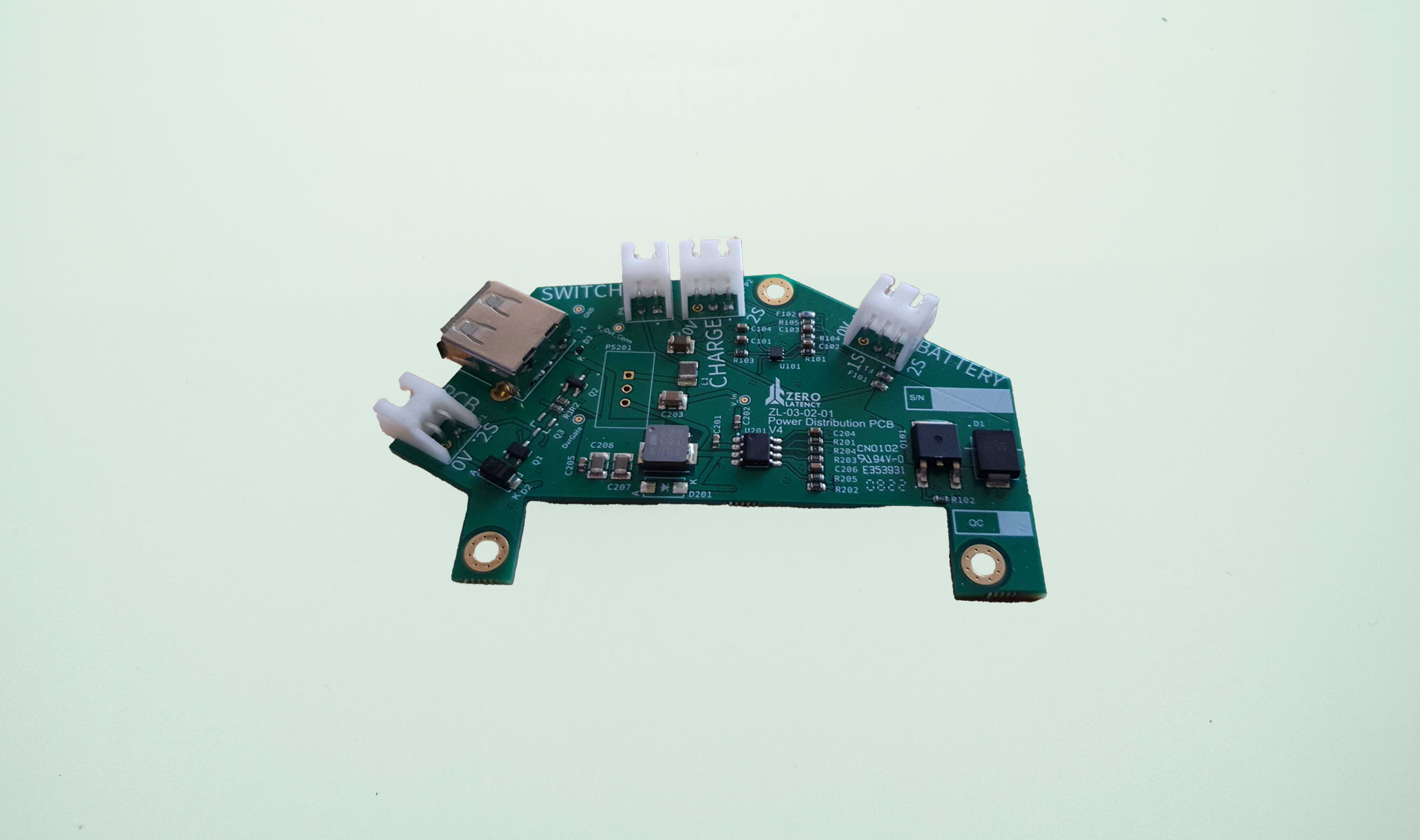 |
| Mode A | Mode Select button (right chassis). | 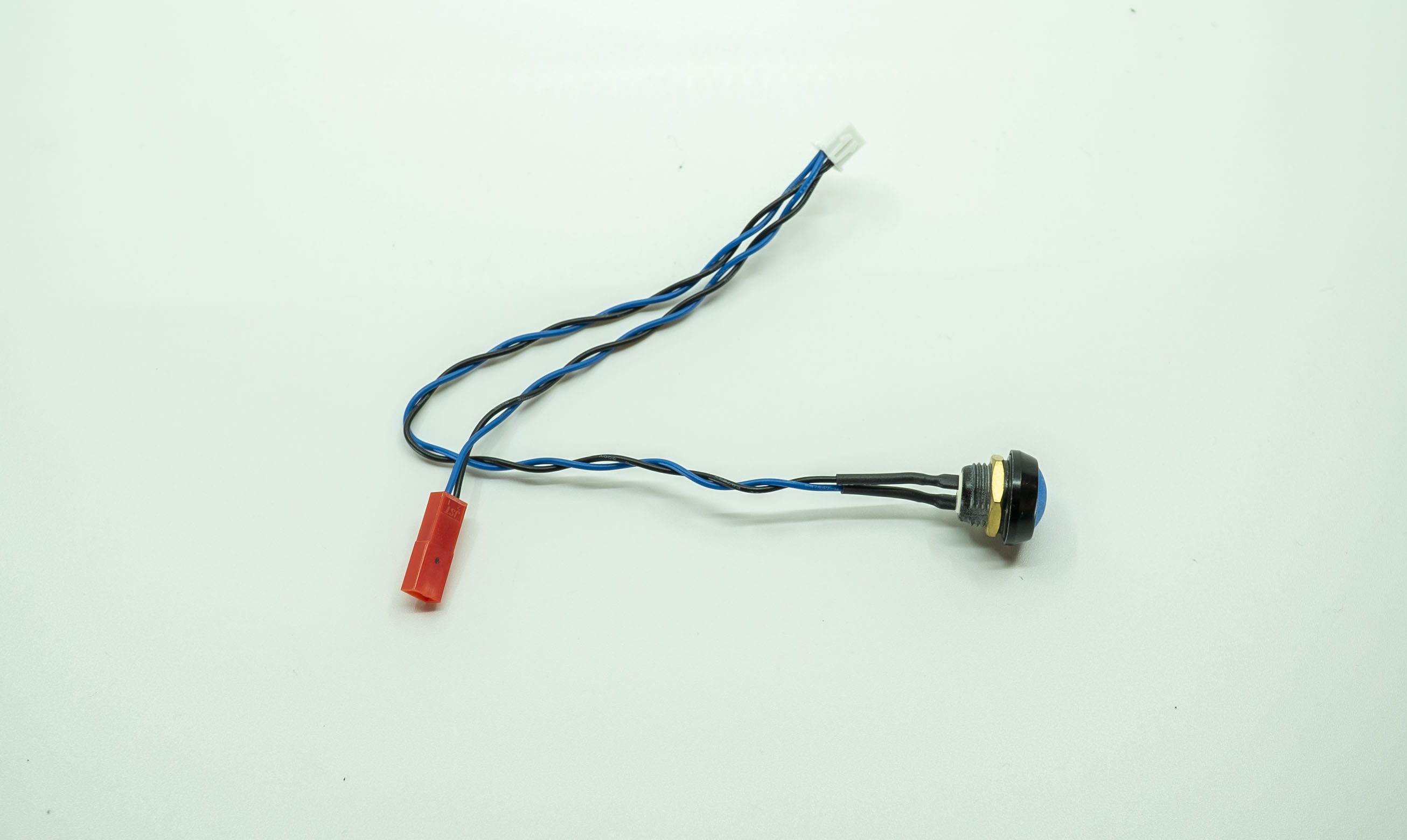 |
| Mode B | Mode Select button (left chassis). | 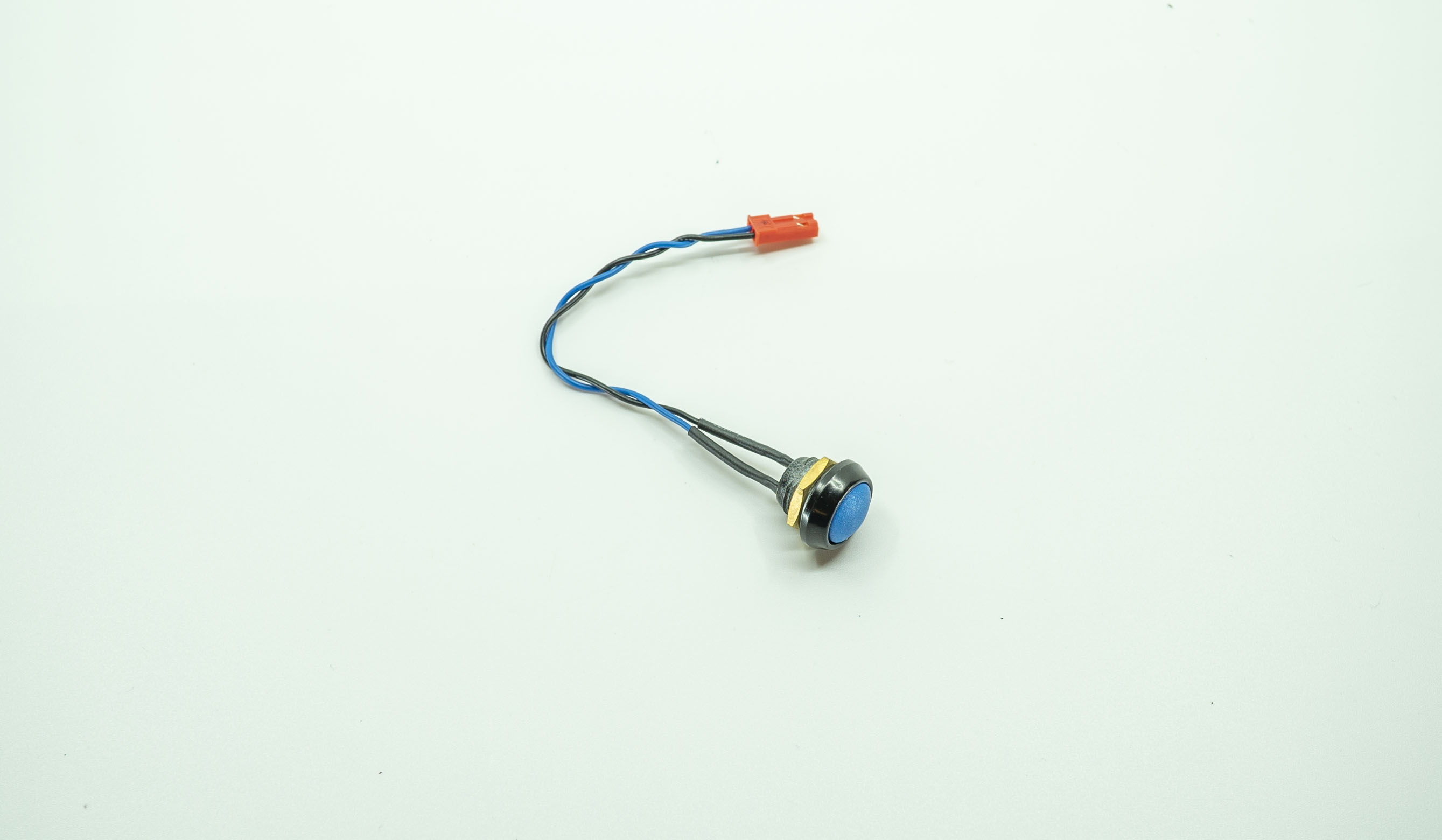 |
| Reload | Reloads the weapons in the games. | 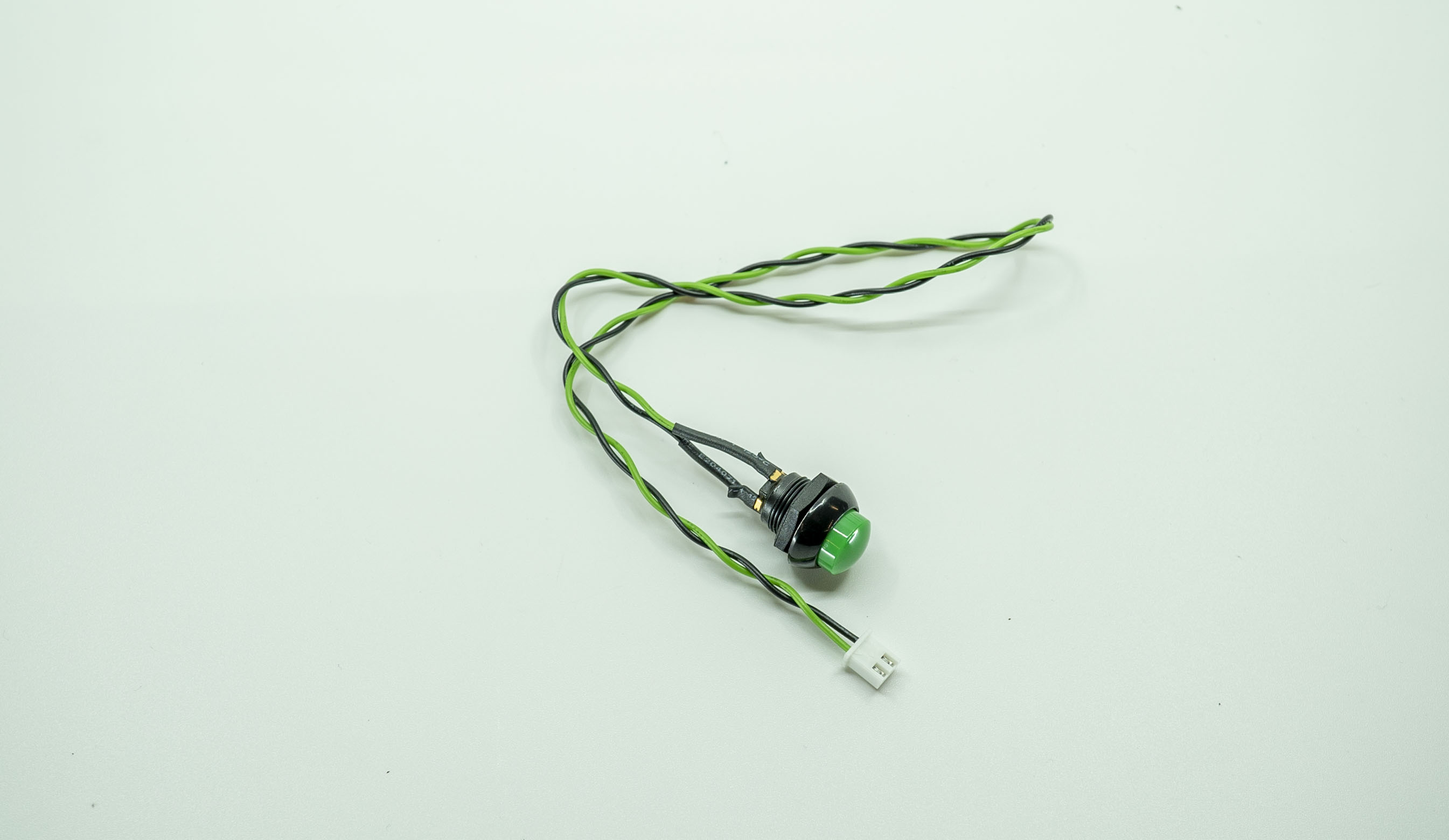 |
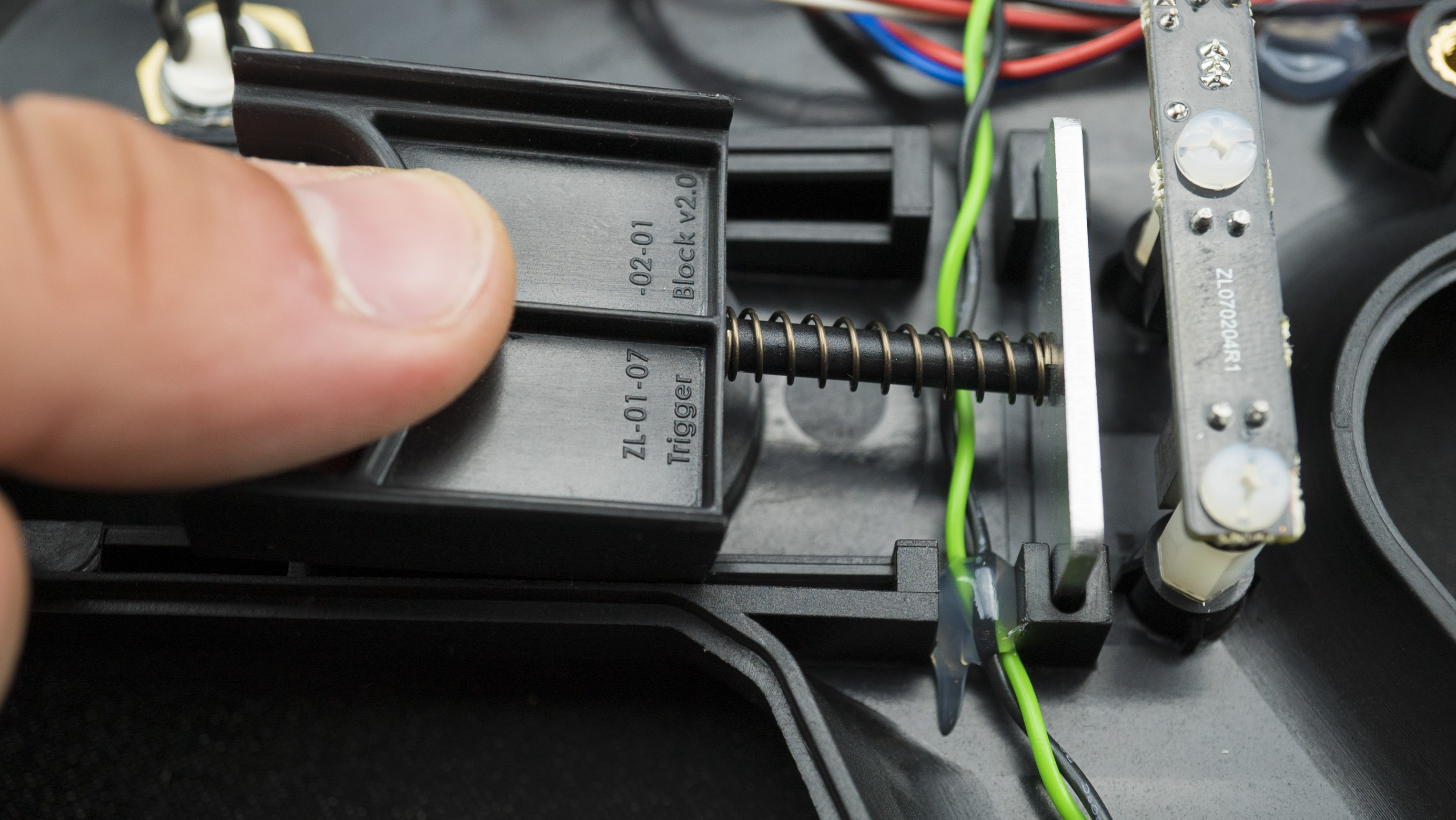
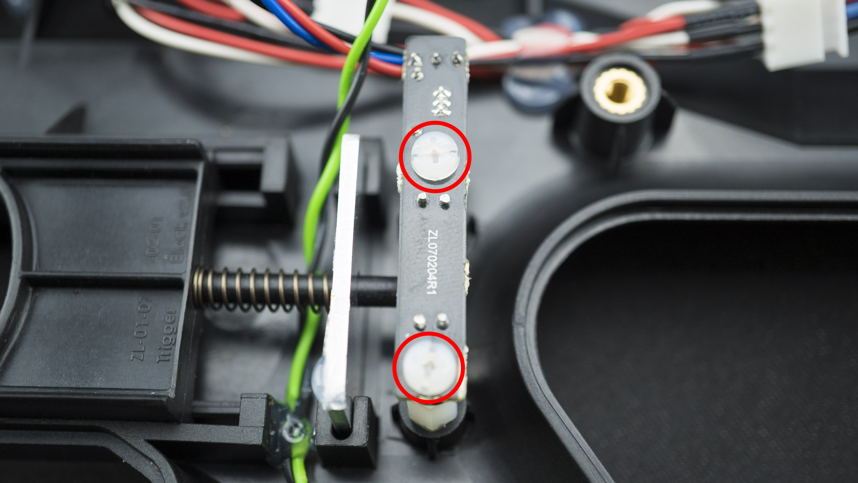
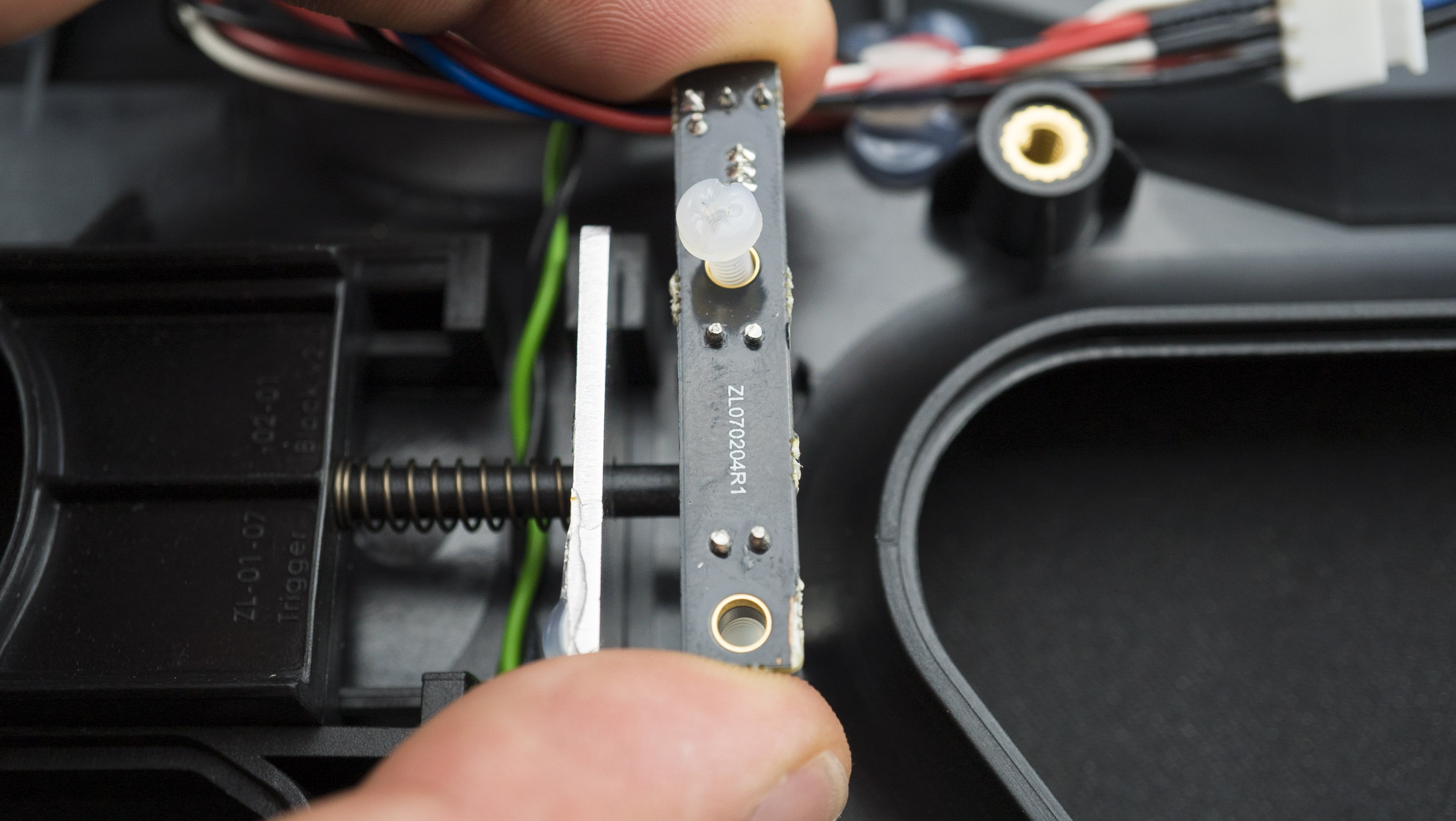
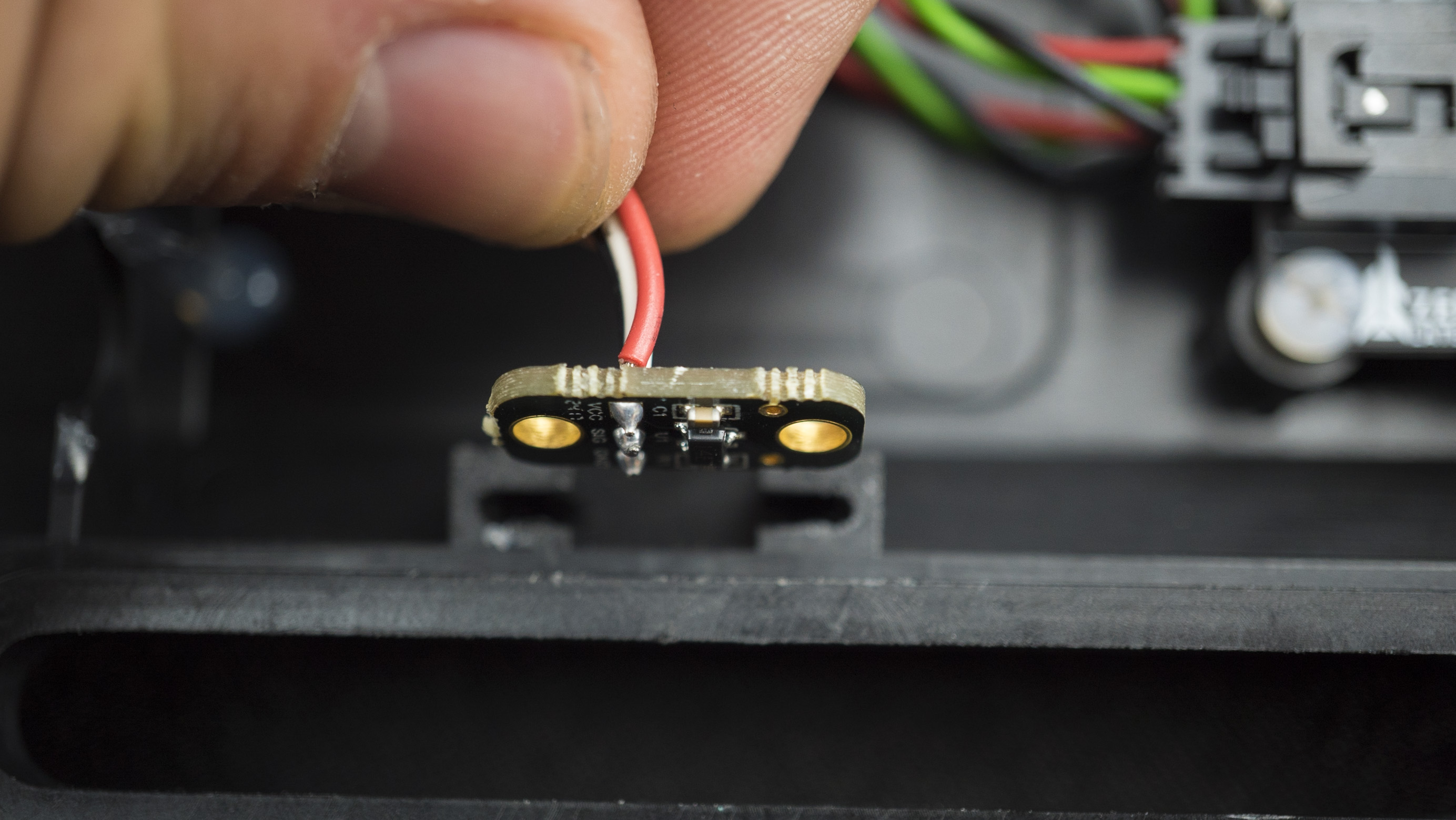
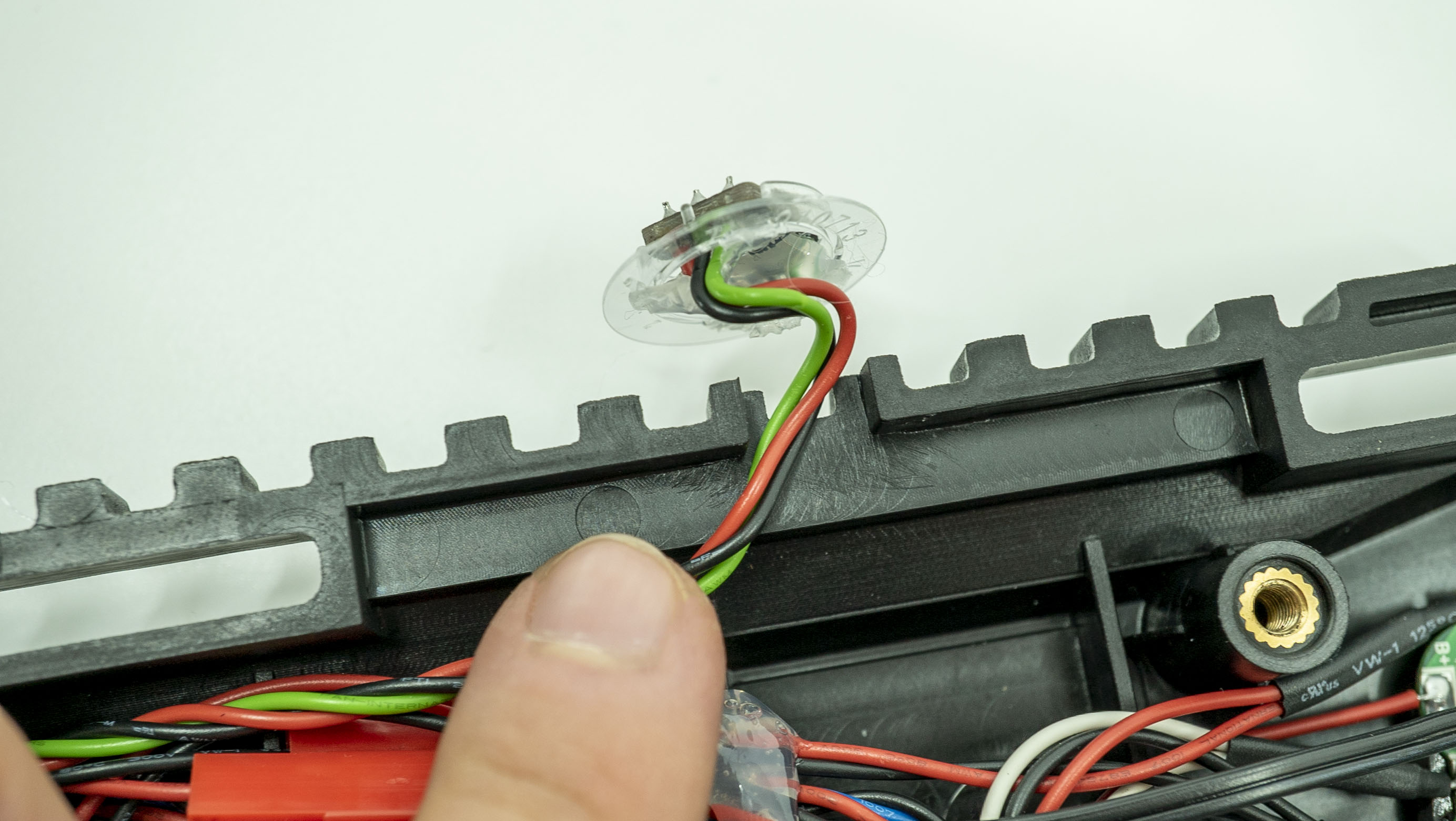
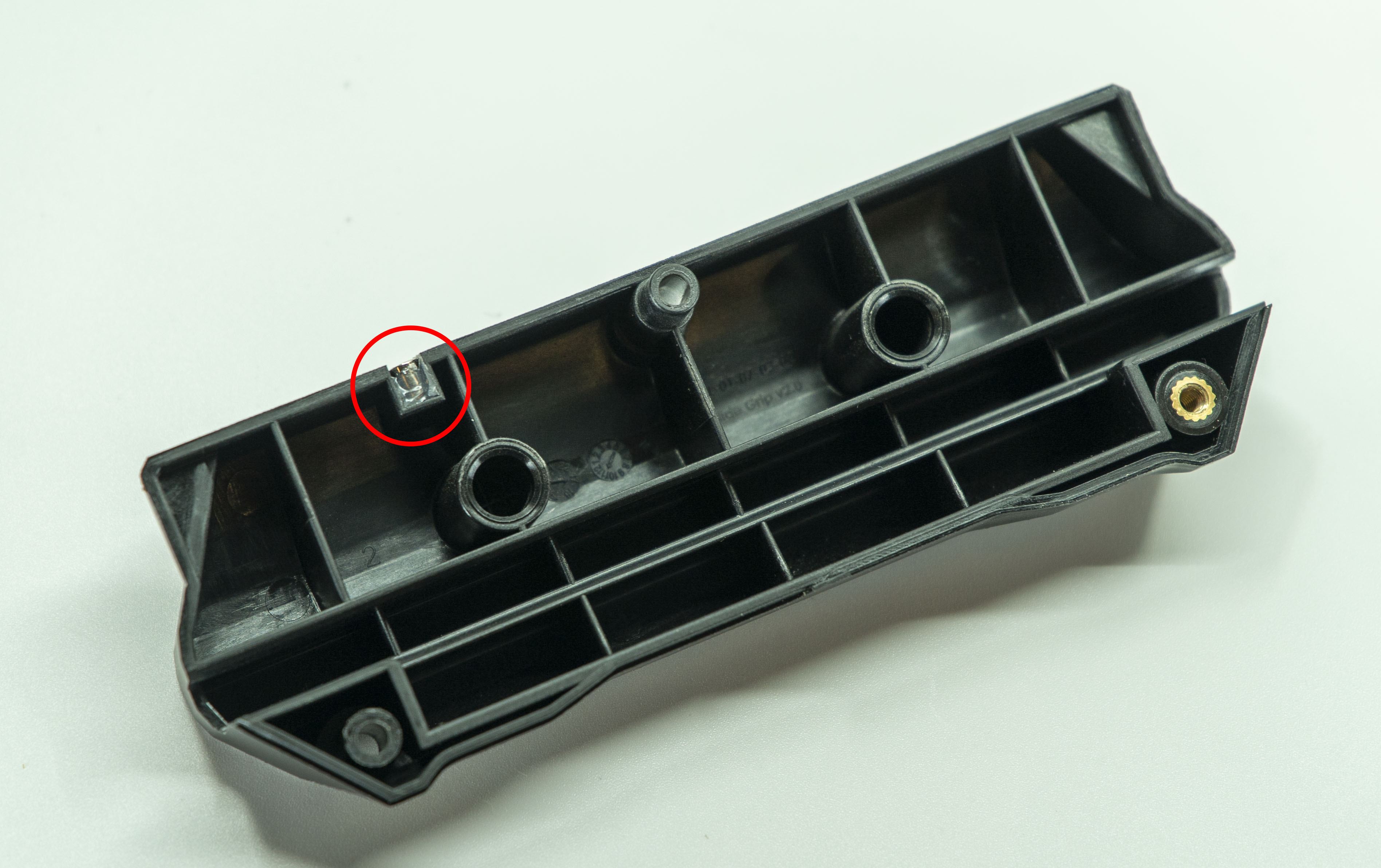
| Trigger | Optical switch for Trigger operation with a pin. | 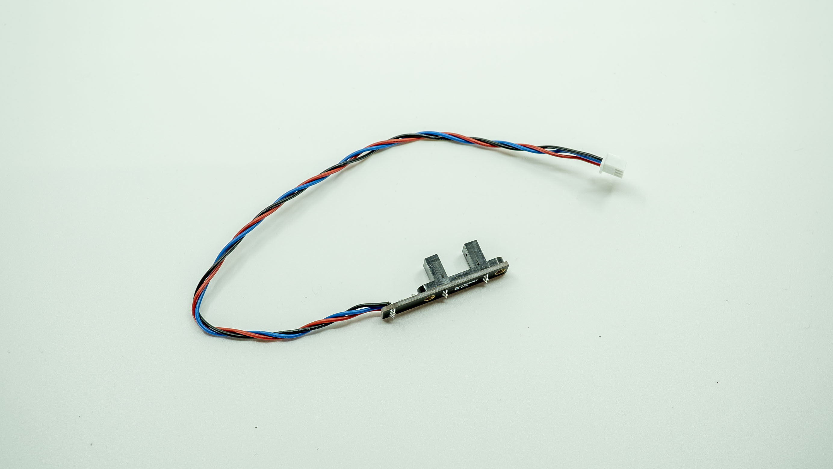 |
| Pump A | Front magnetic switch for pump slide operation. | 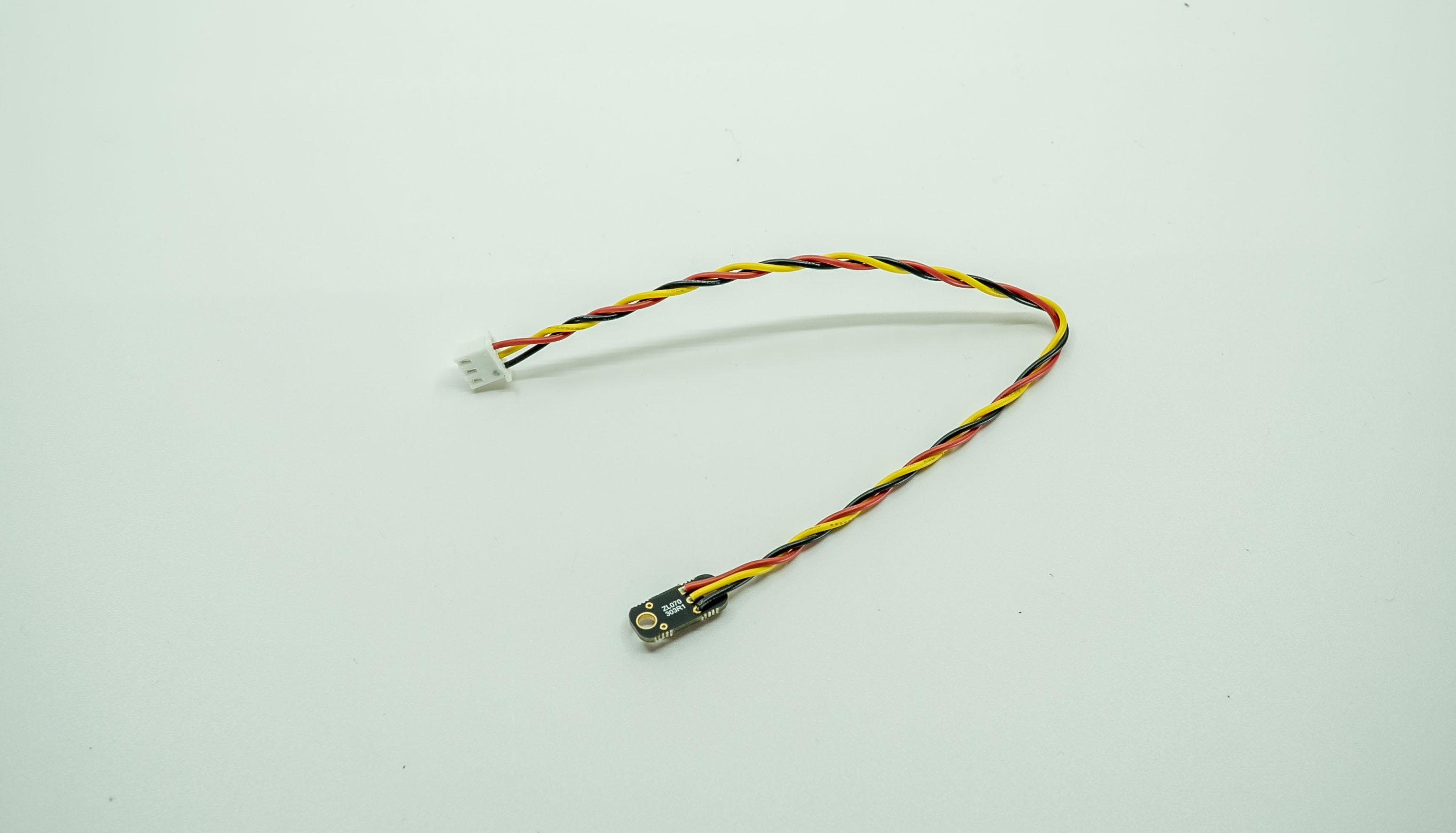 |
| Pump B | Rear magnetic switch for pump slide operation. | 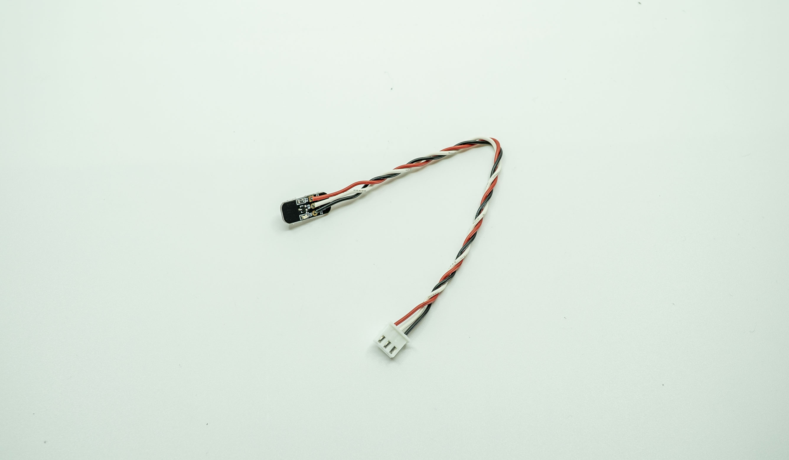 |
| LED | Wiring loom for the Raptor LED. | 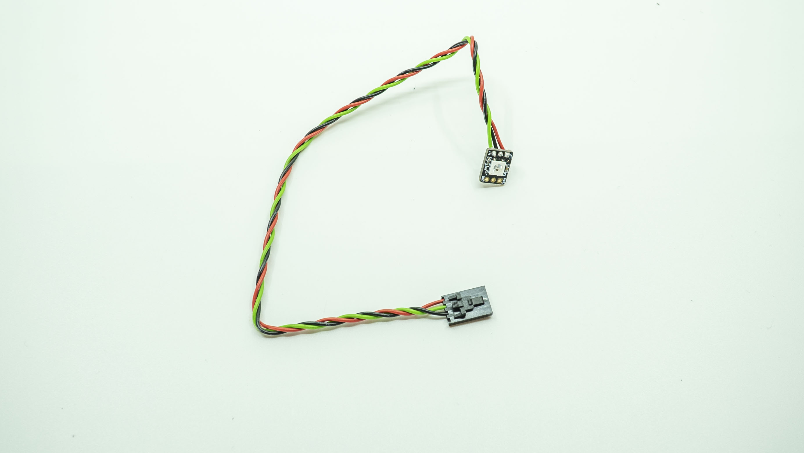 |
| Battery | Gives the controller power. | 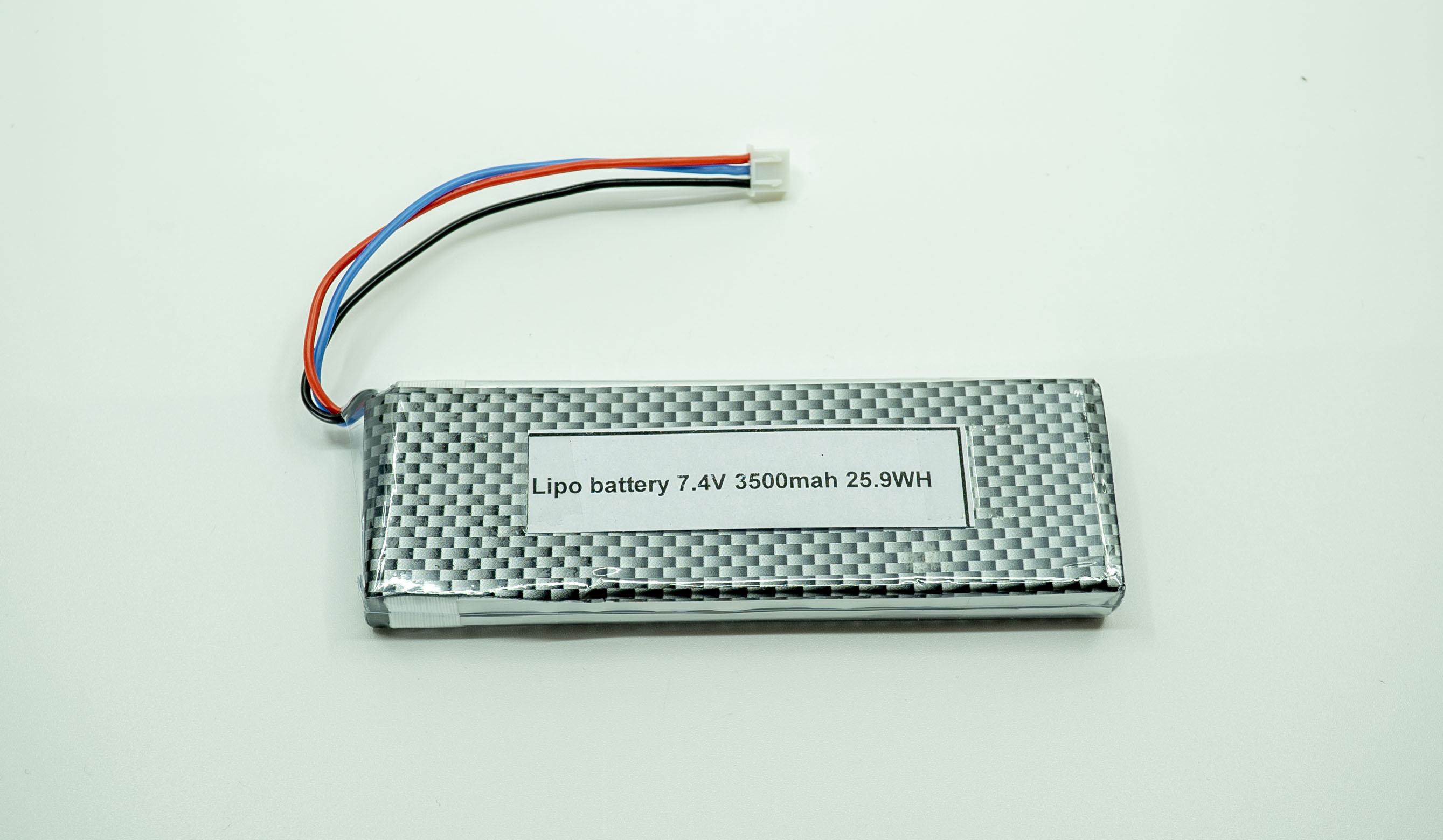 |
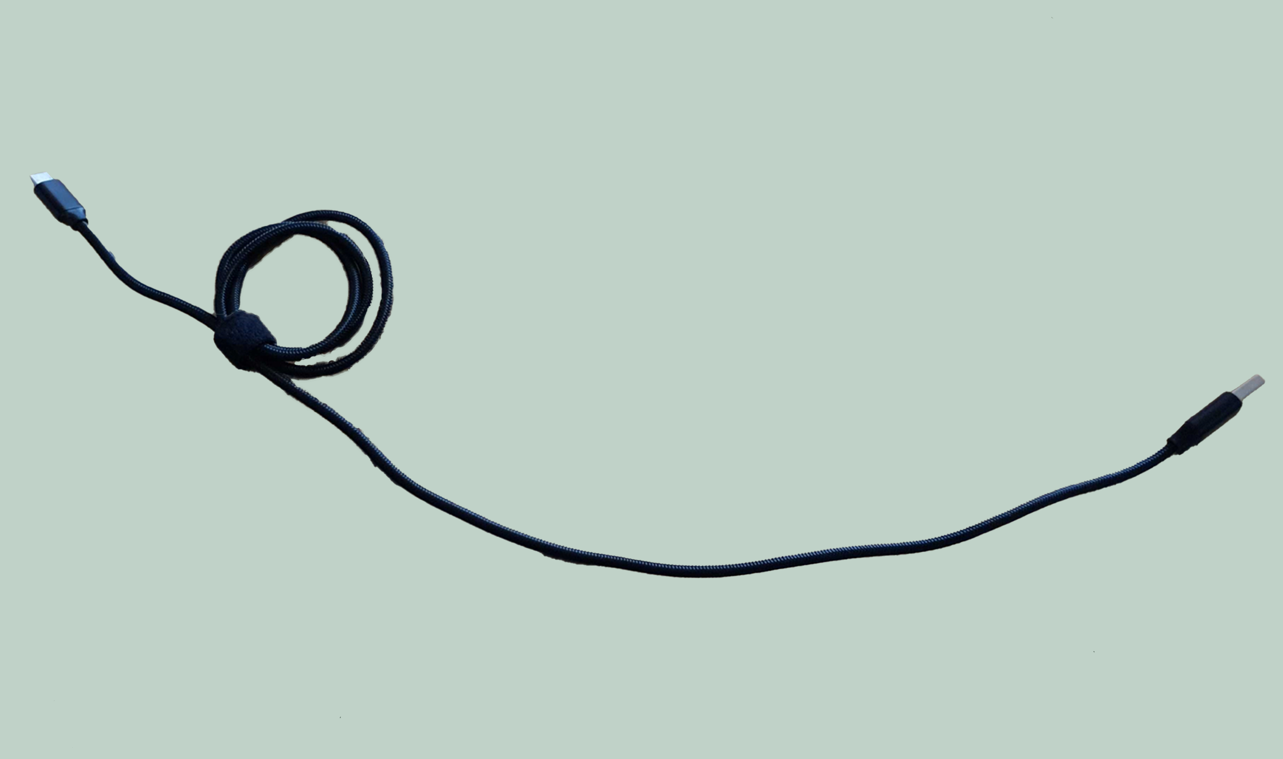
| USB C cable | Connects the Tracker to the battery. |
|
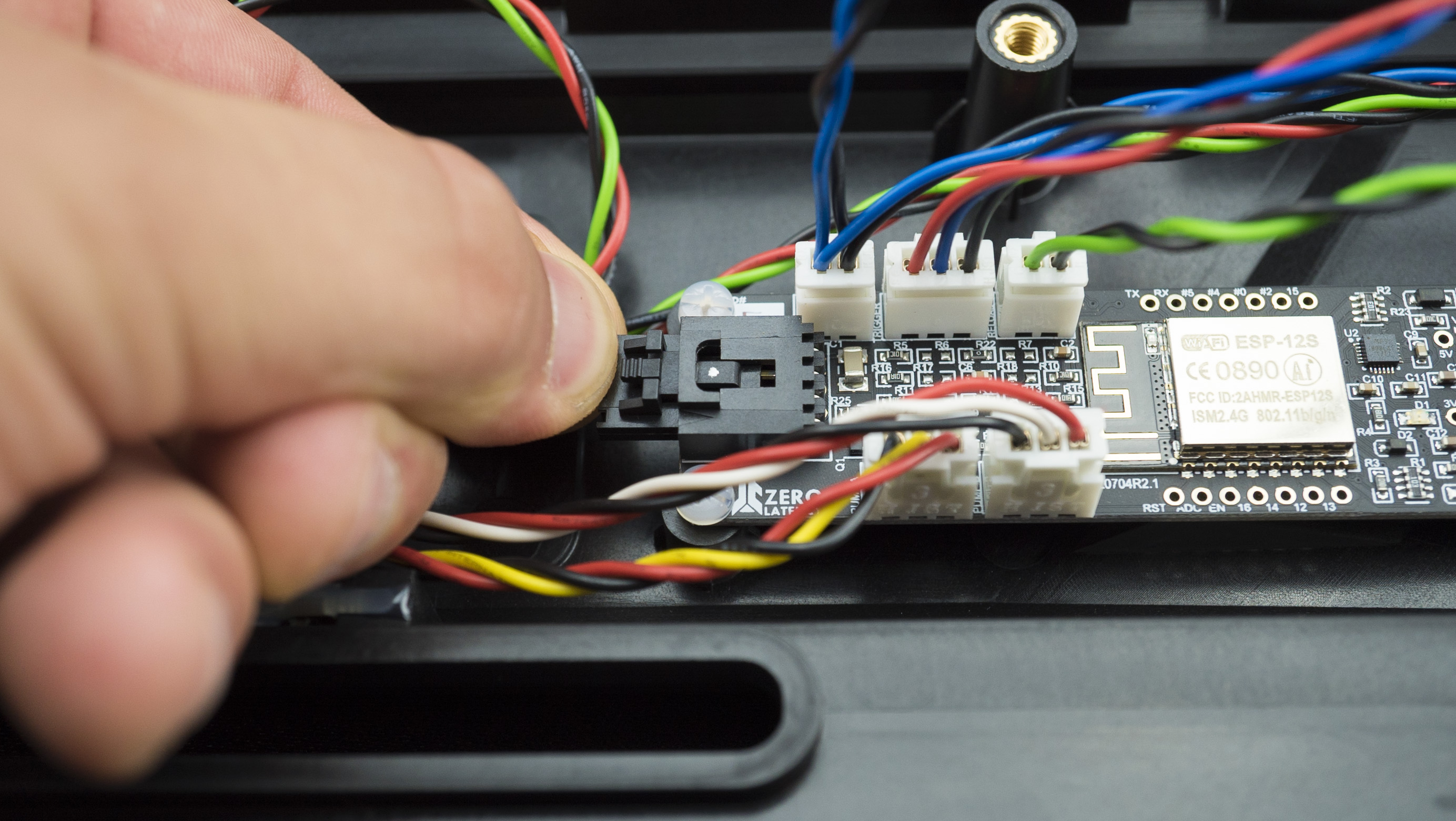
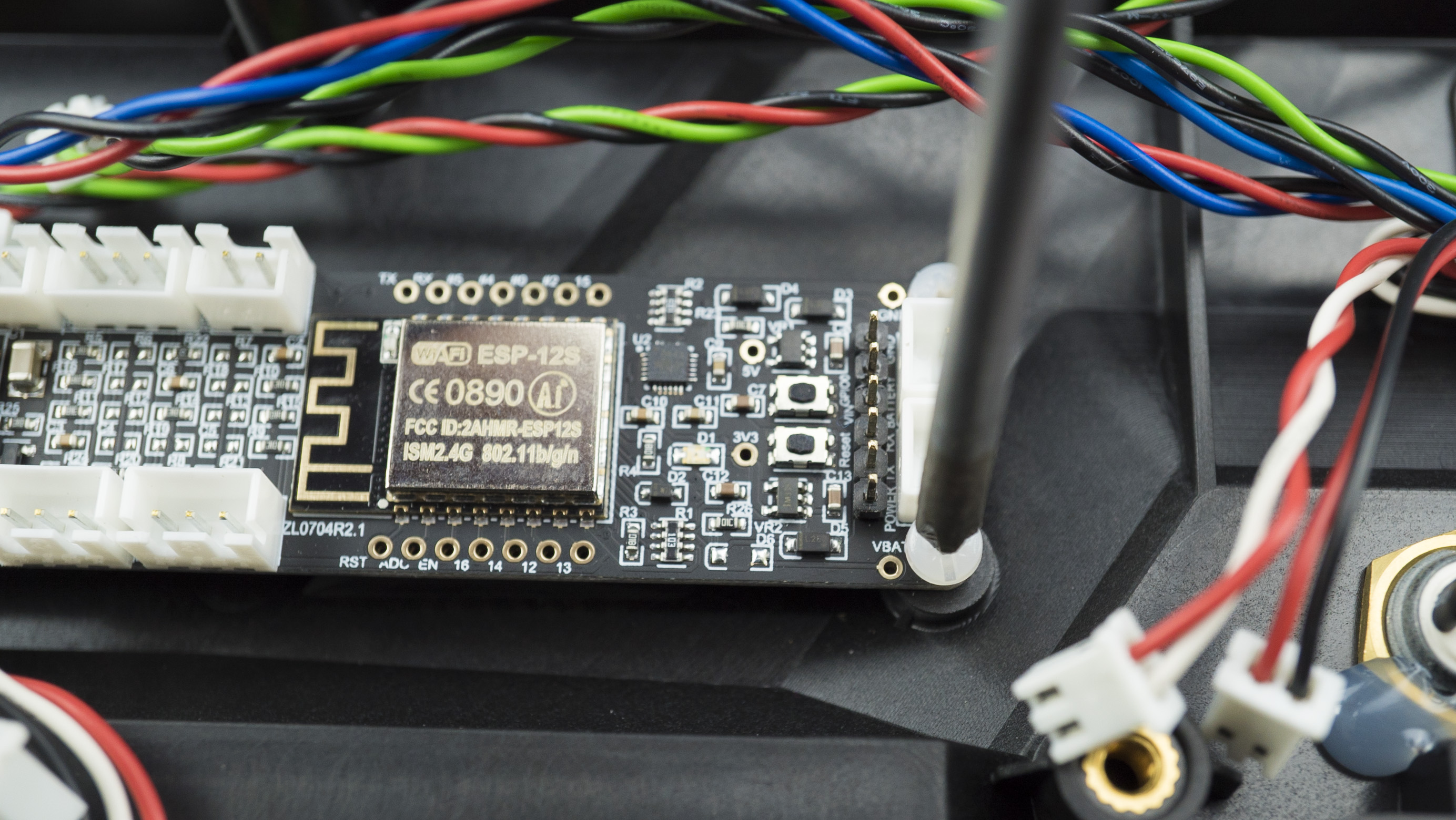
| Master PCB | Controls all the inputs and outputs of the controller. | 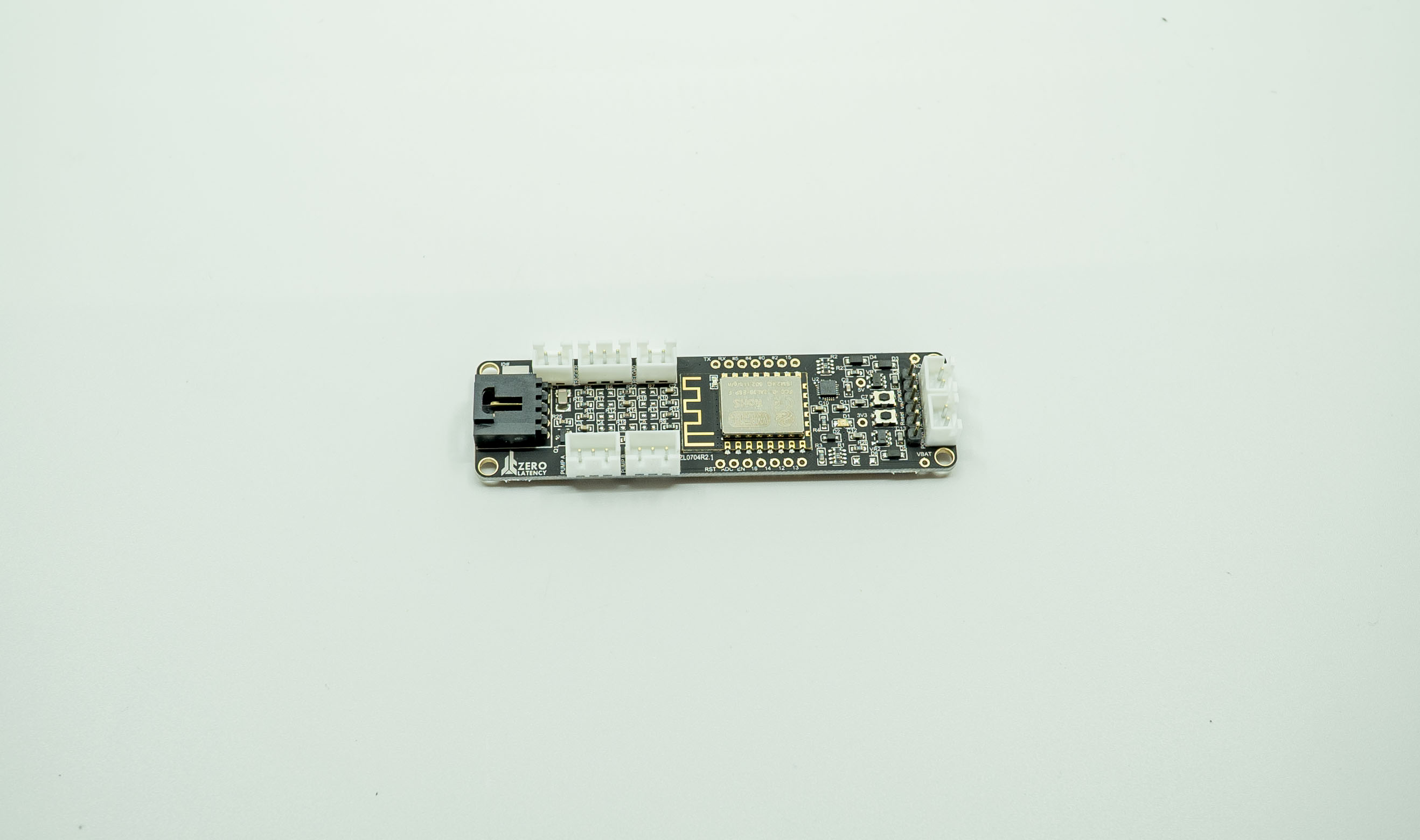 |
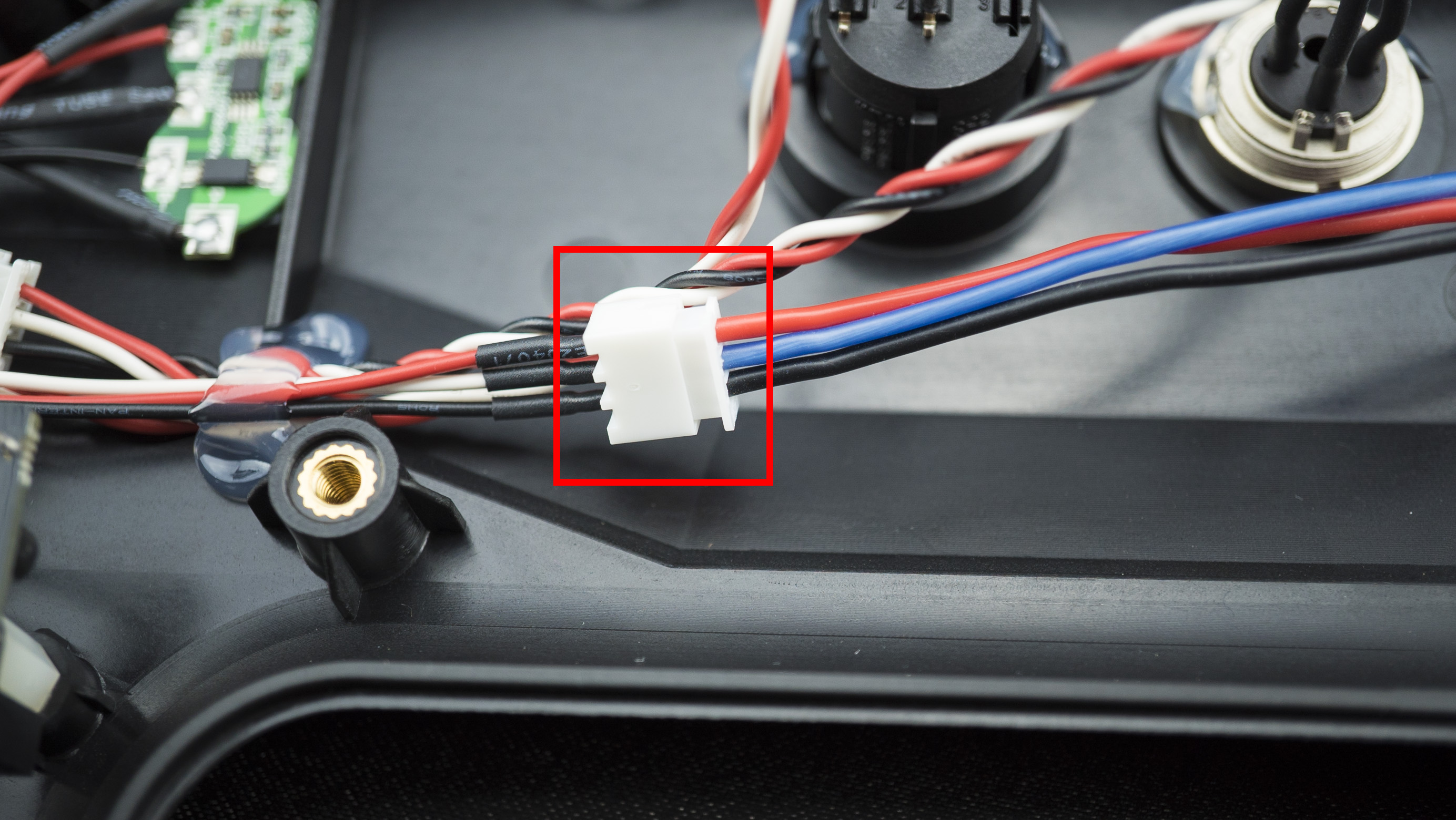
Where do I connect the cables on the PCB?
This is each connection on the PCB:

What are the symptoms?
- The buttons are not working when they are pressed.
- The pump action is not working.
Step 1: Debug Mode
- Press and hold the Reload button, Mode Select button and power the controller on.
- The LED will glow red then let go of the Reload button and Mode Select button.
- Test each button and the pump. The LED light should change colour in the following order:
- Red
- Green
- Blue
- Cyan
- Yellow
- Magenta
- Bright White
- Dim White
- LED Off
- When the test is complete, power off the controller.

Do all the buttons and the pump work?
- Return the backpack to operations.
This did not resolve the issue
- Continue to Step 2.
Step 2: Open the controller
- Take out the Tracker.
- Disconnect the USB C cable.
- Using the 3mm Hex head attachment and torque driver, remove the screw on the Tracker mount.
- Slide the Tracker mount off.
- Remove the bottom six screws and then remove the last bottom screw (it is the shortest on the controller).
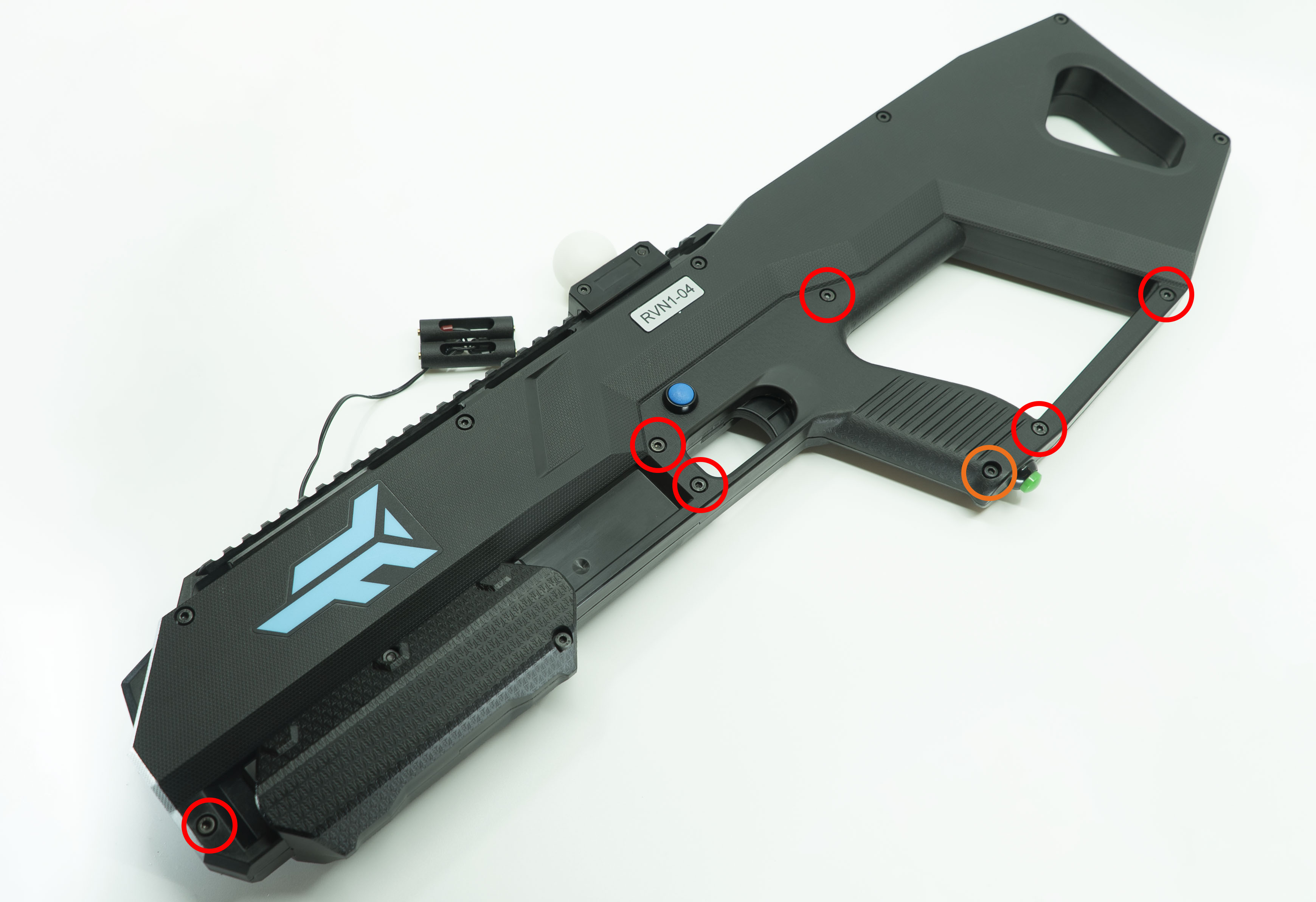
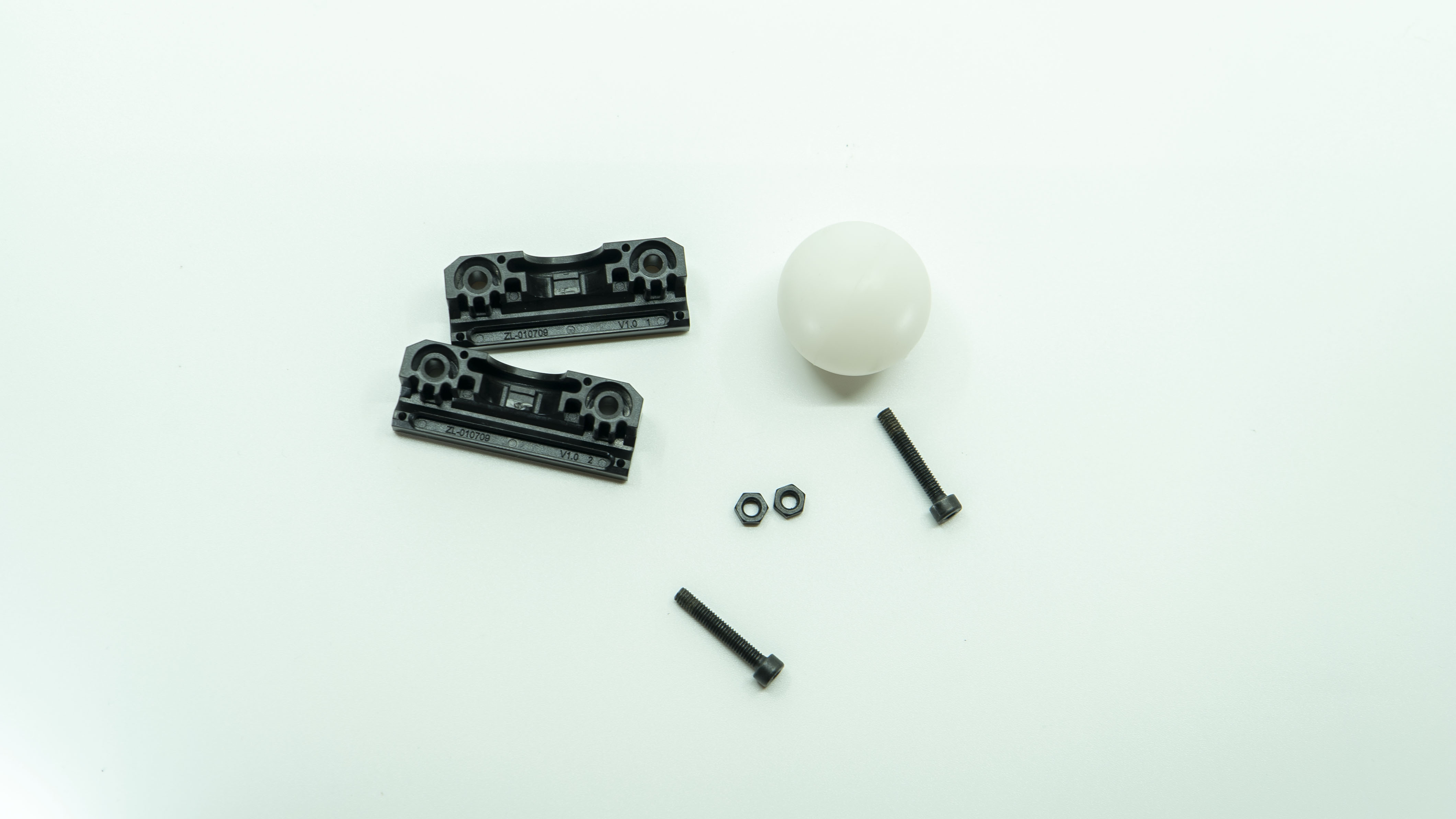
- Remove the two screws and nuts on the LED tracking ball clamp, separate the LED tracking ball clamp and remove the tracking ball from the LED seat.


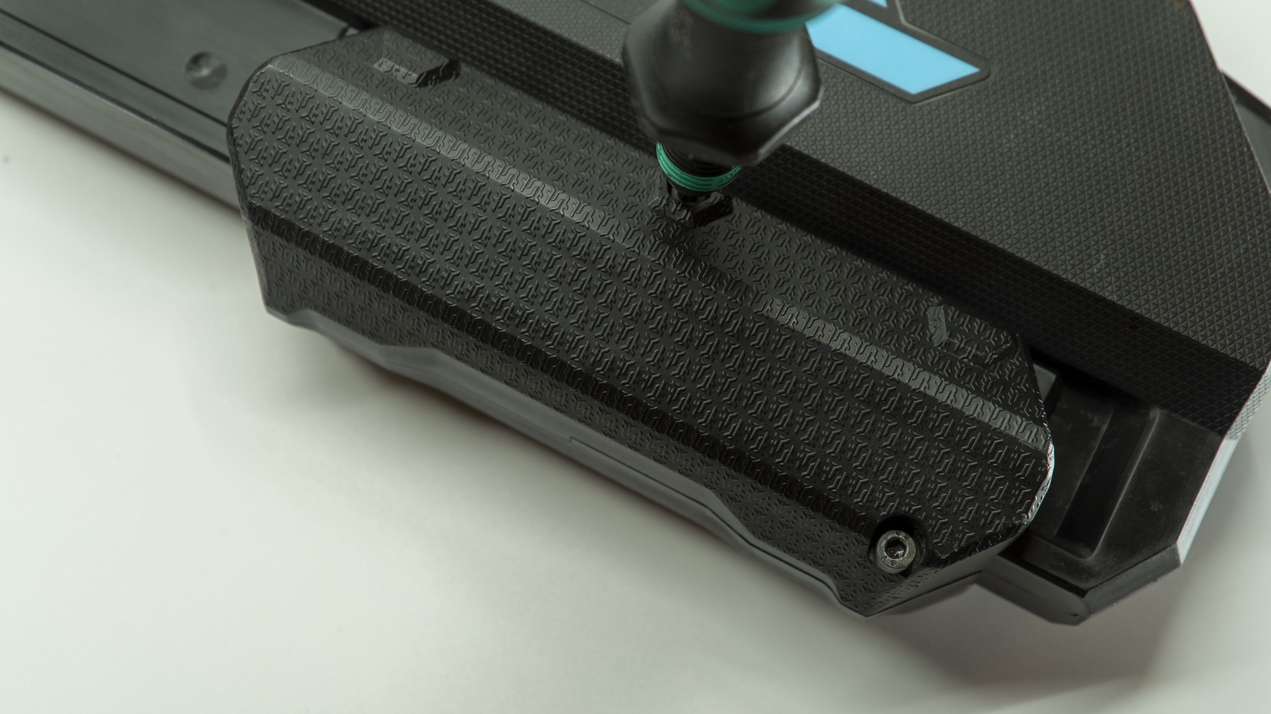
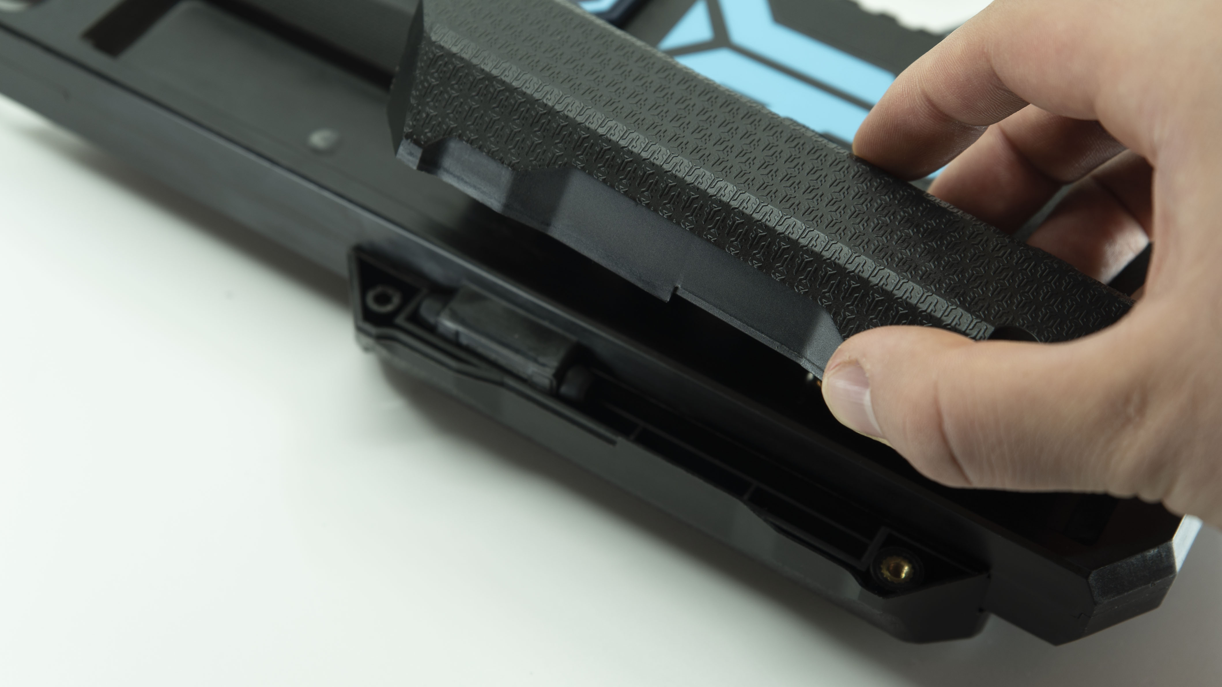
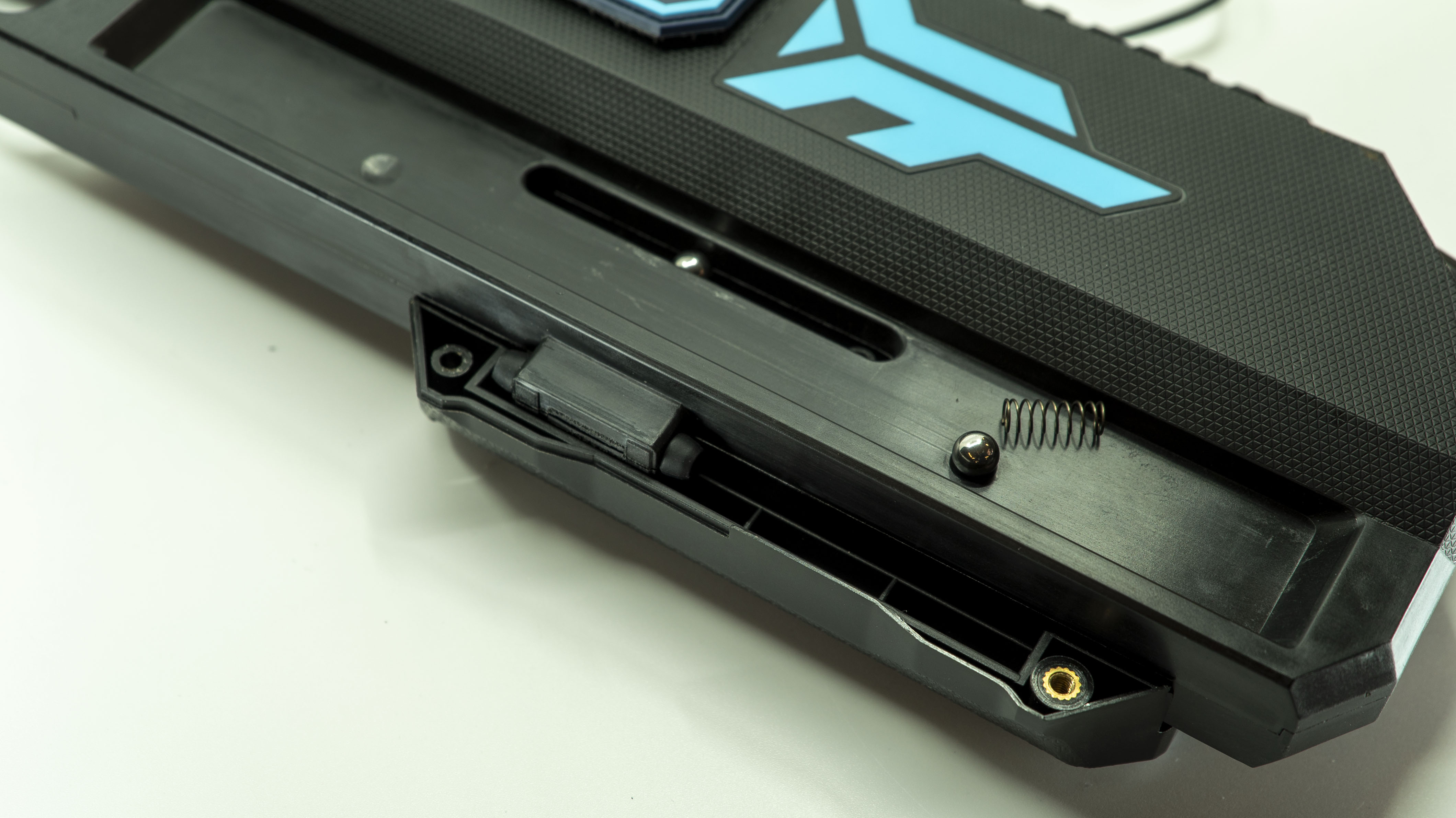
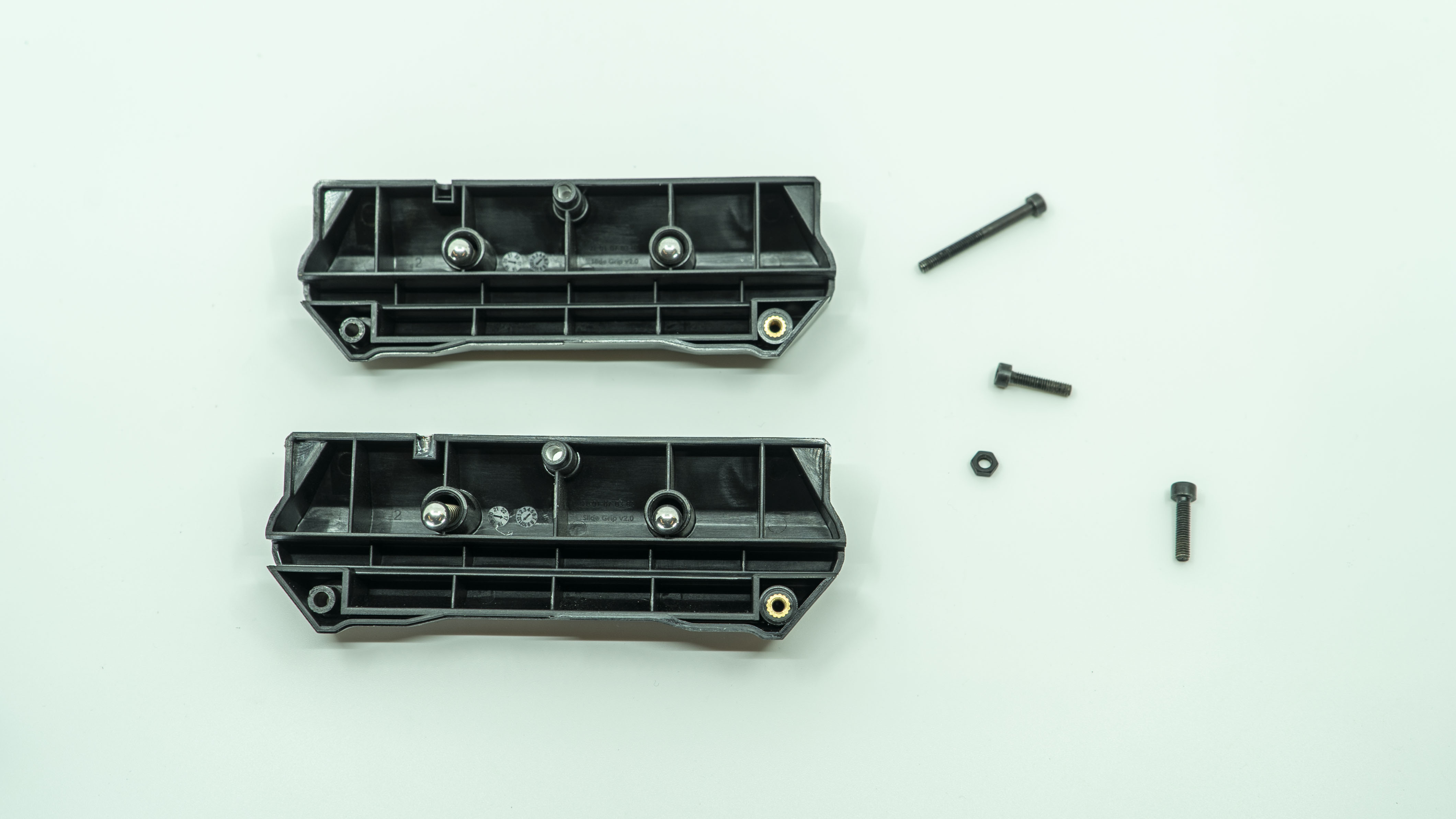
- Remove the three screws from the slide grips, separate the grips (there will be two ball bearings and two springs on each side.
- Remove the top six screws.
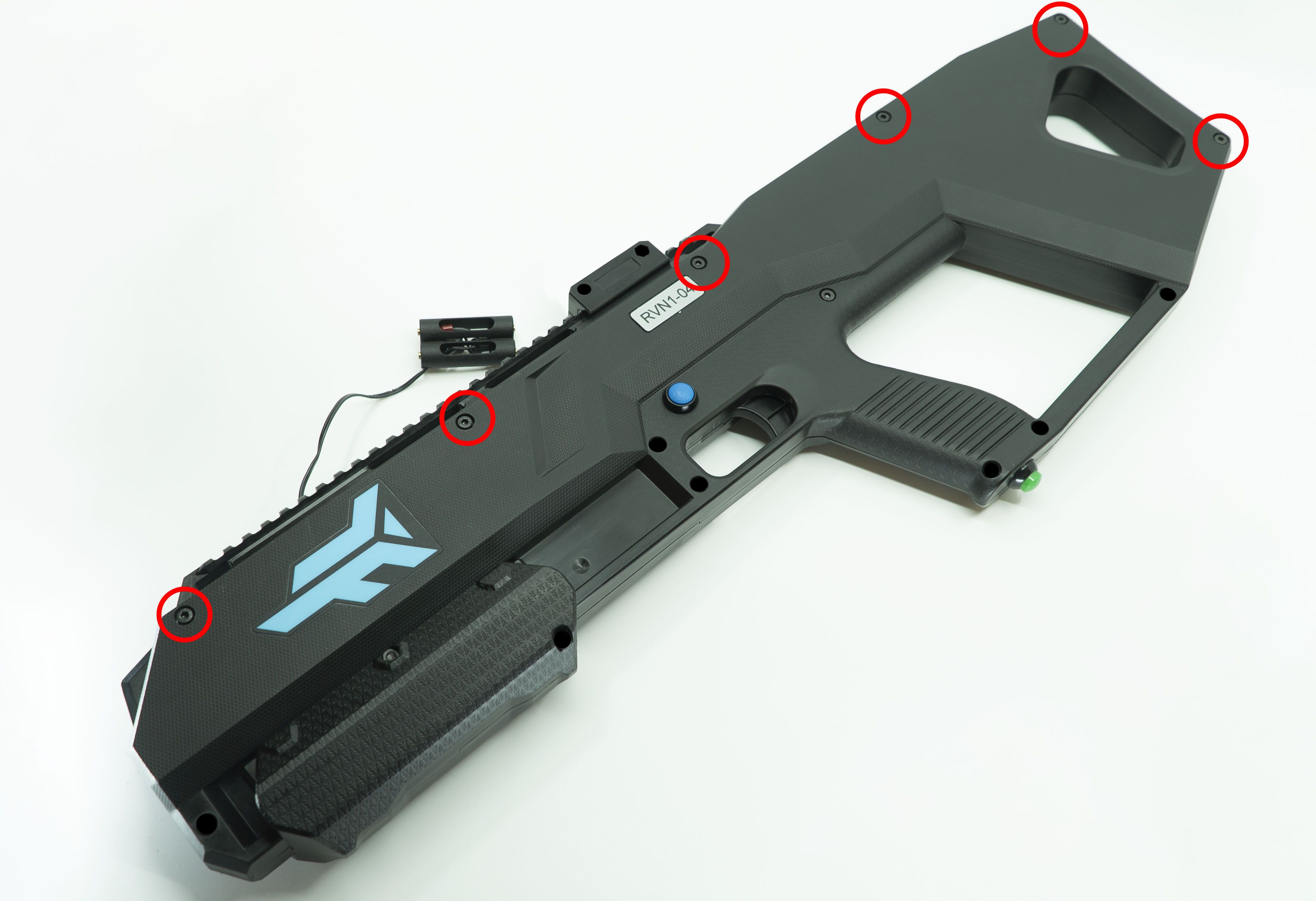
- Separate the two halves of the controller (keep note that the mode select button will be connected).
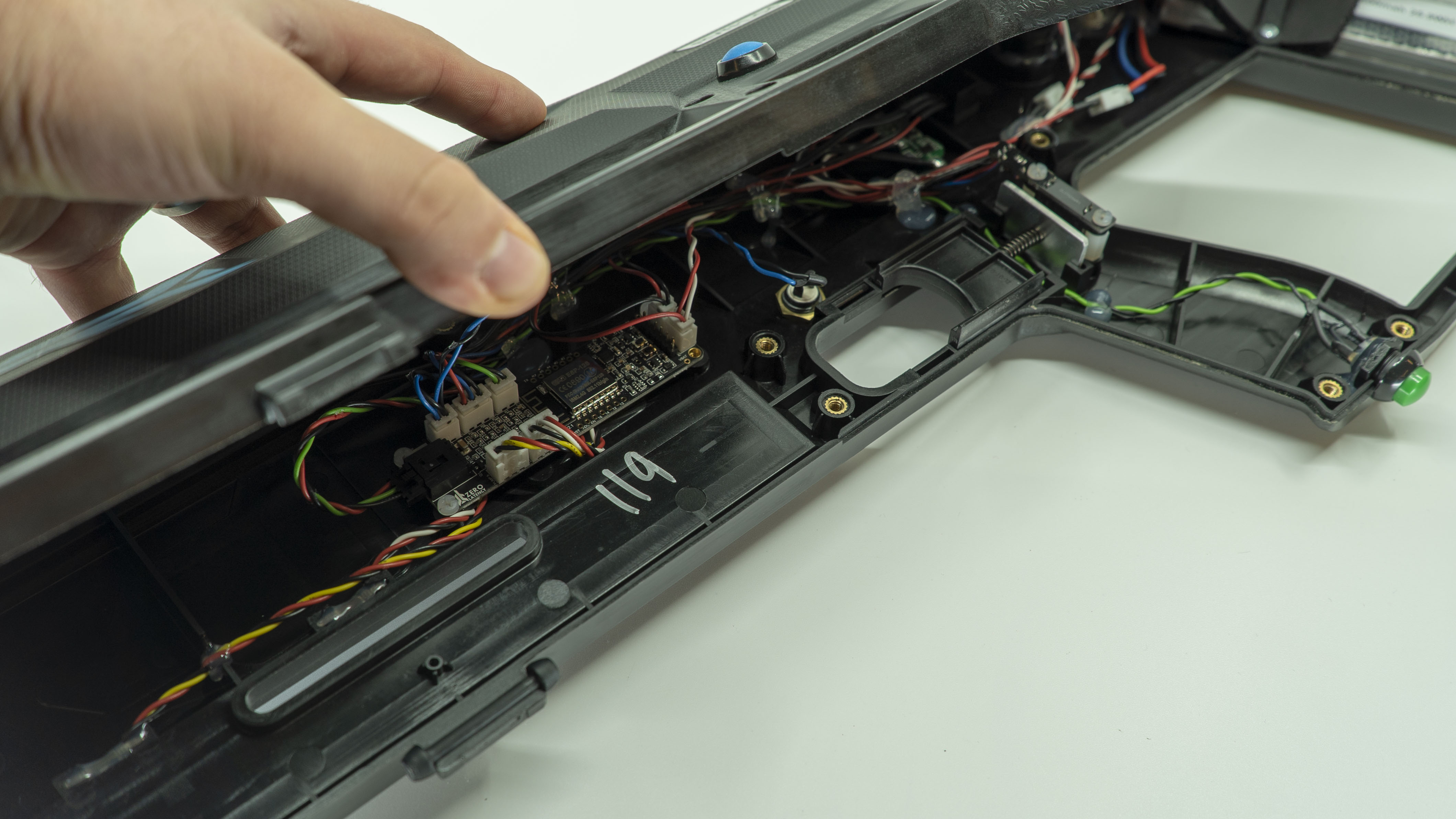
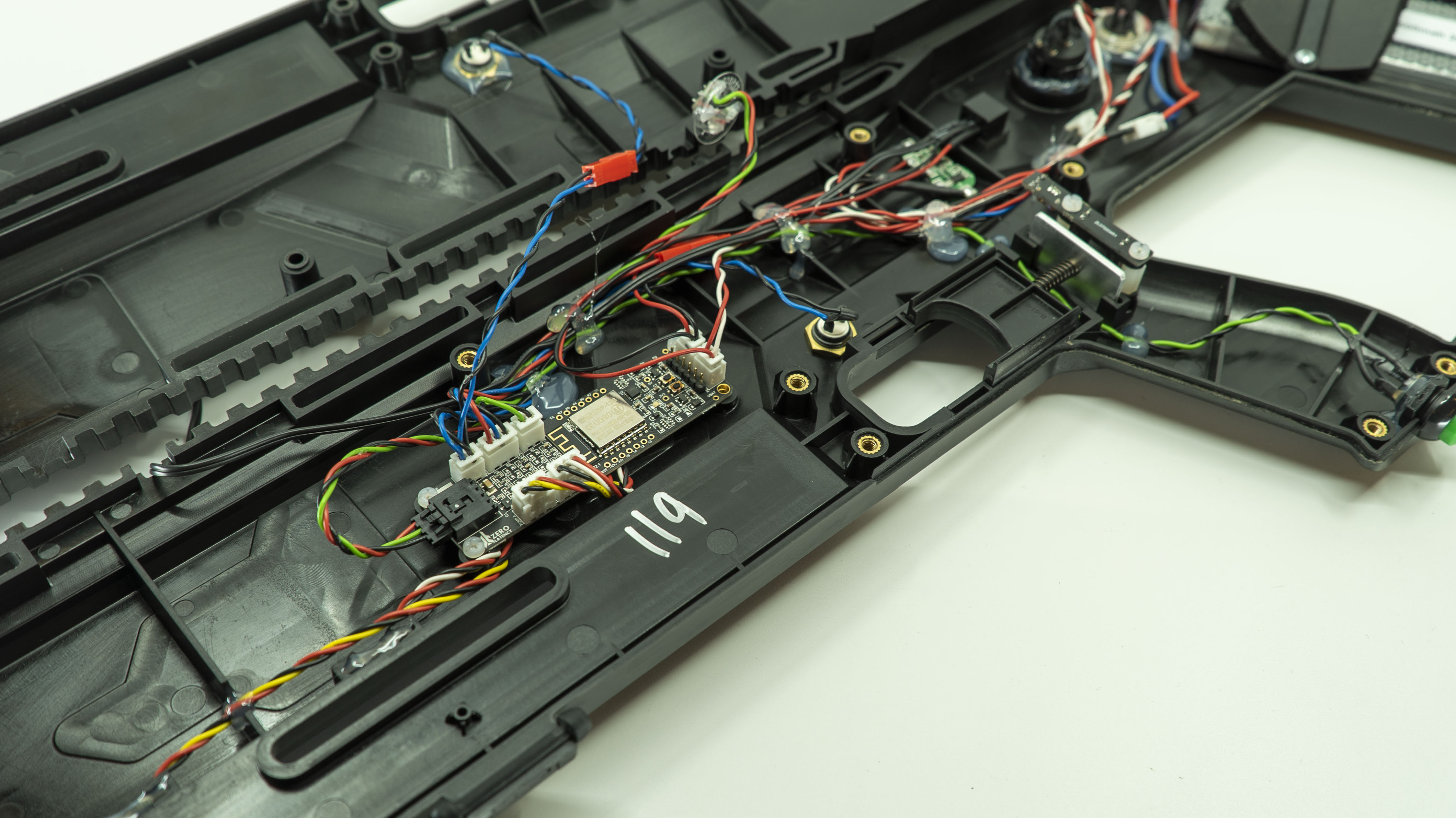
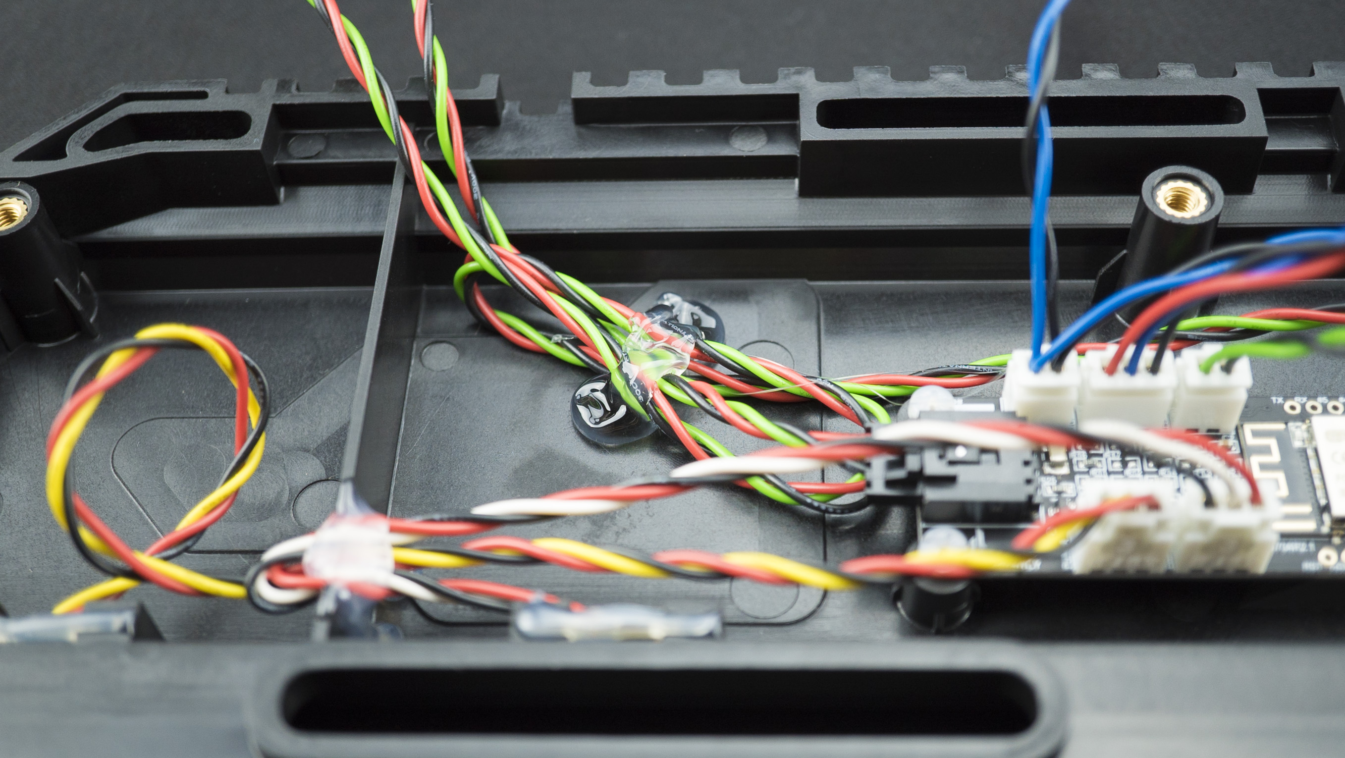
Step 3: Master PCB connections
- Carefully inspect each cable and ensure it is connected to the master PCB, look out for any damaged cables.
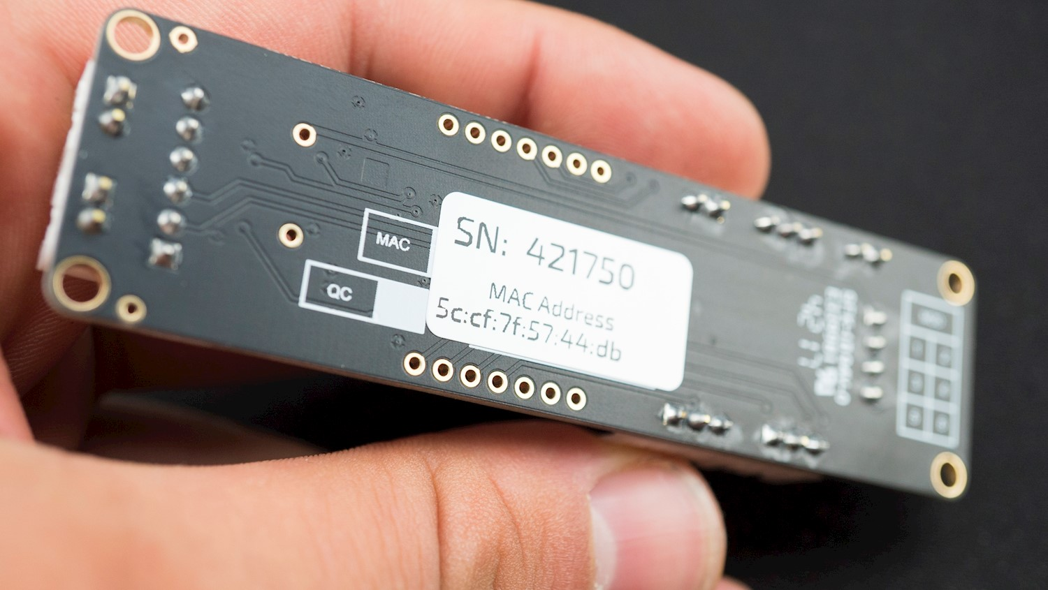
Info
Please record the serial number on the back of the PCB as the Support team may need it.
The cable was unplugged and resolved the issue
- Continue to Step 5.
This did not resolve the issue
- Continue to Step 4.
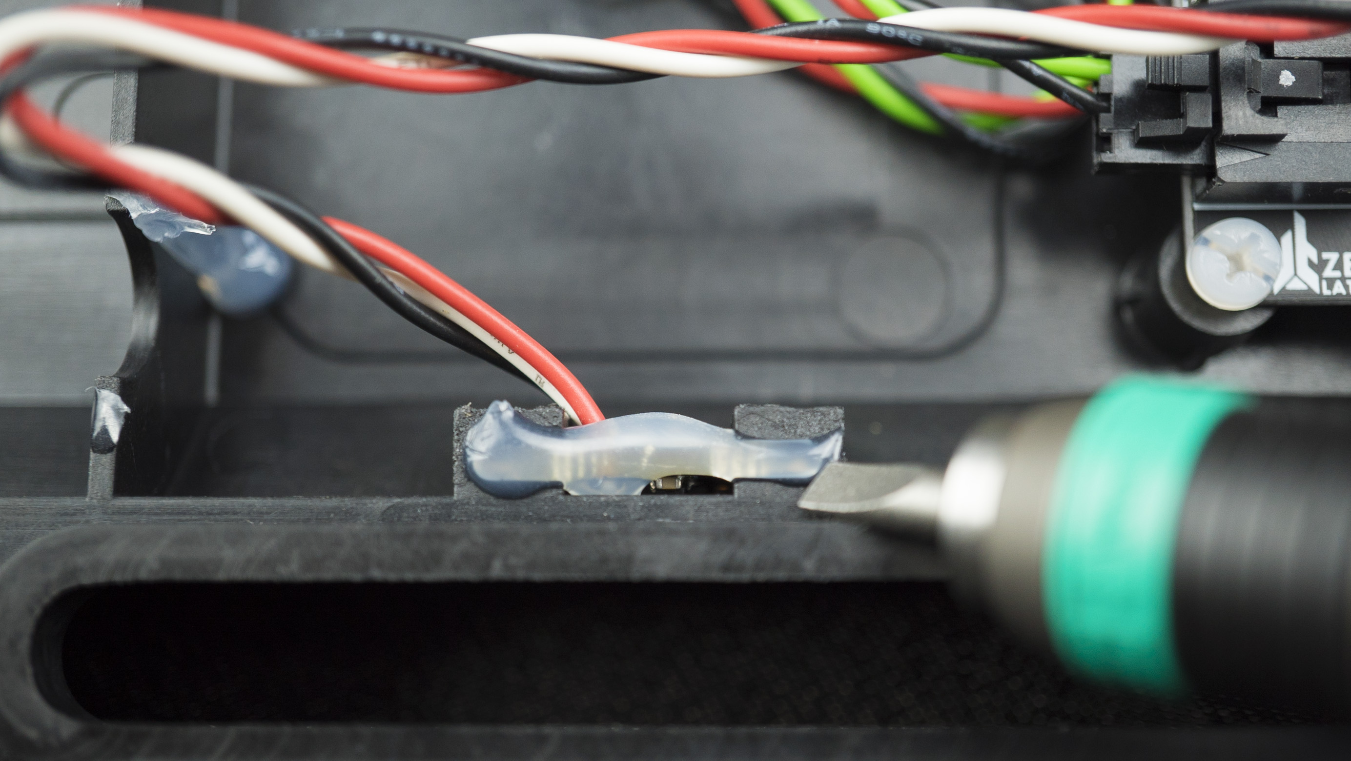
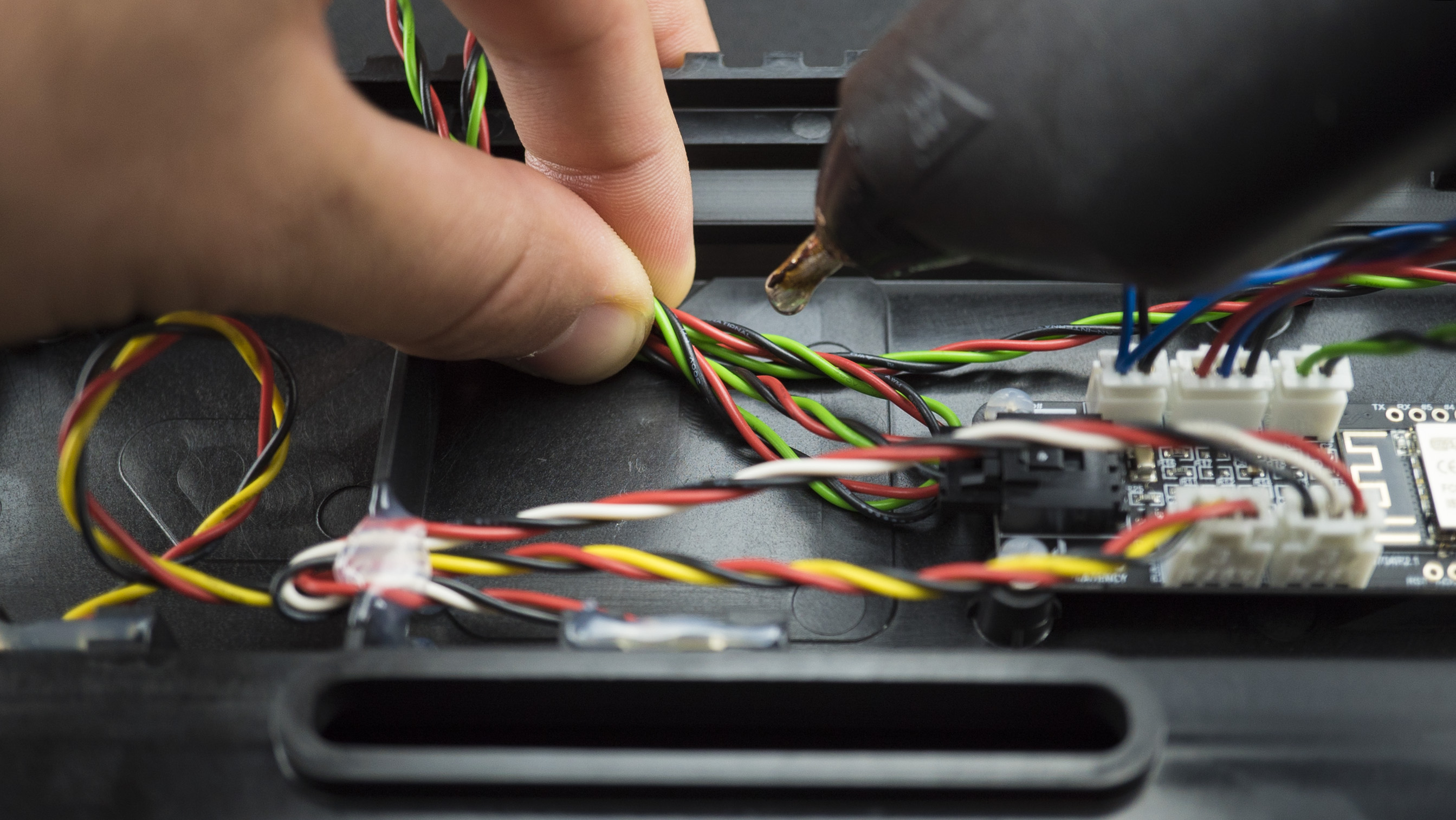
Step 4: Replace the button, cable or battery
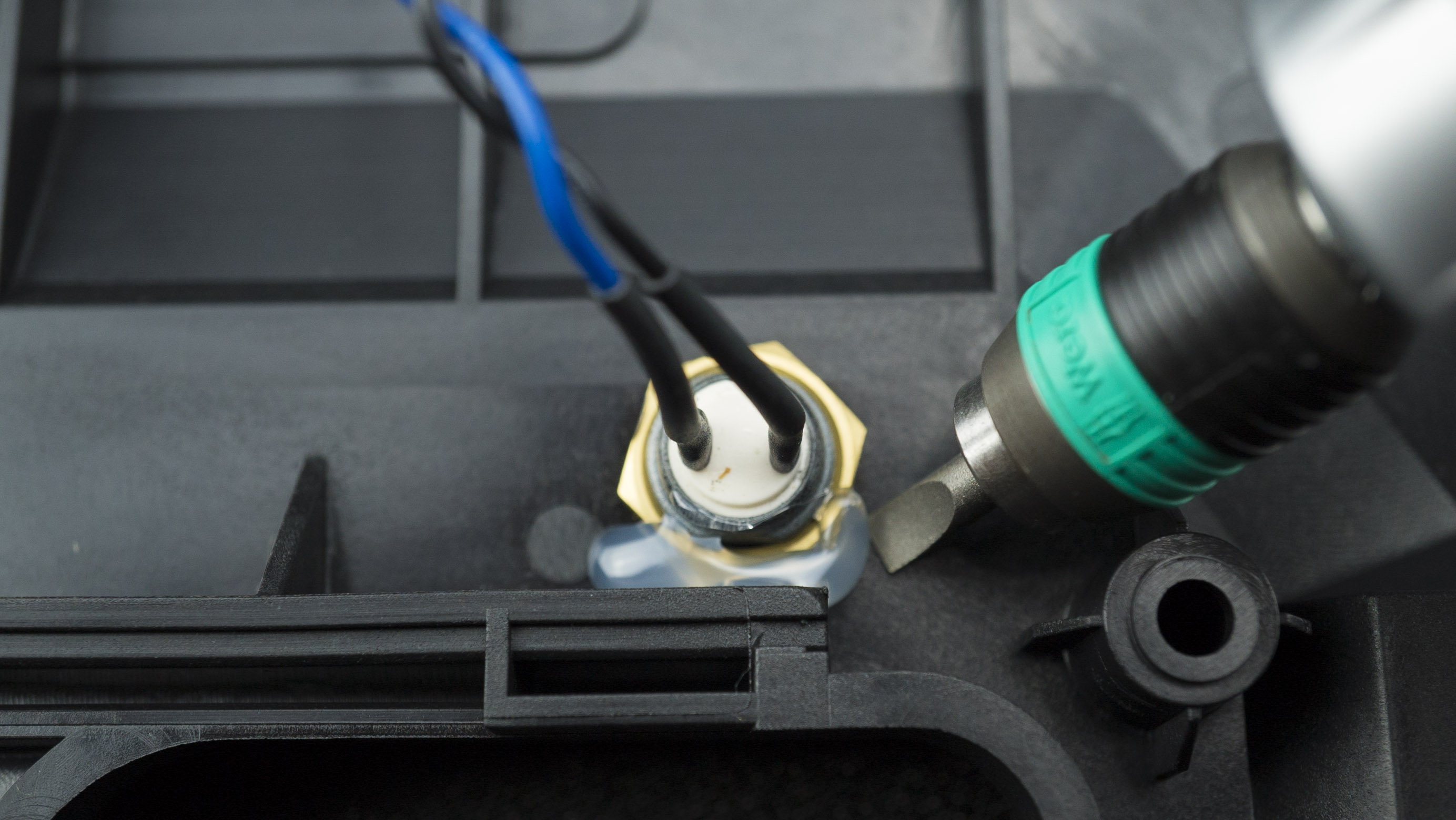
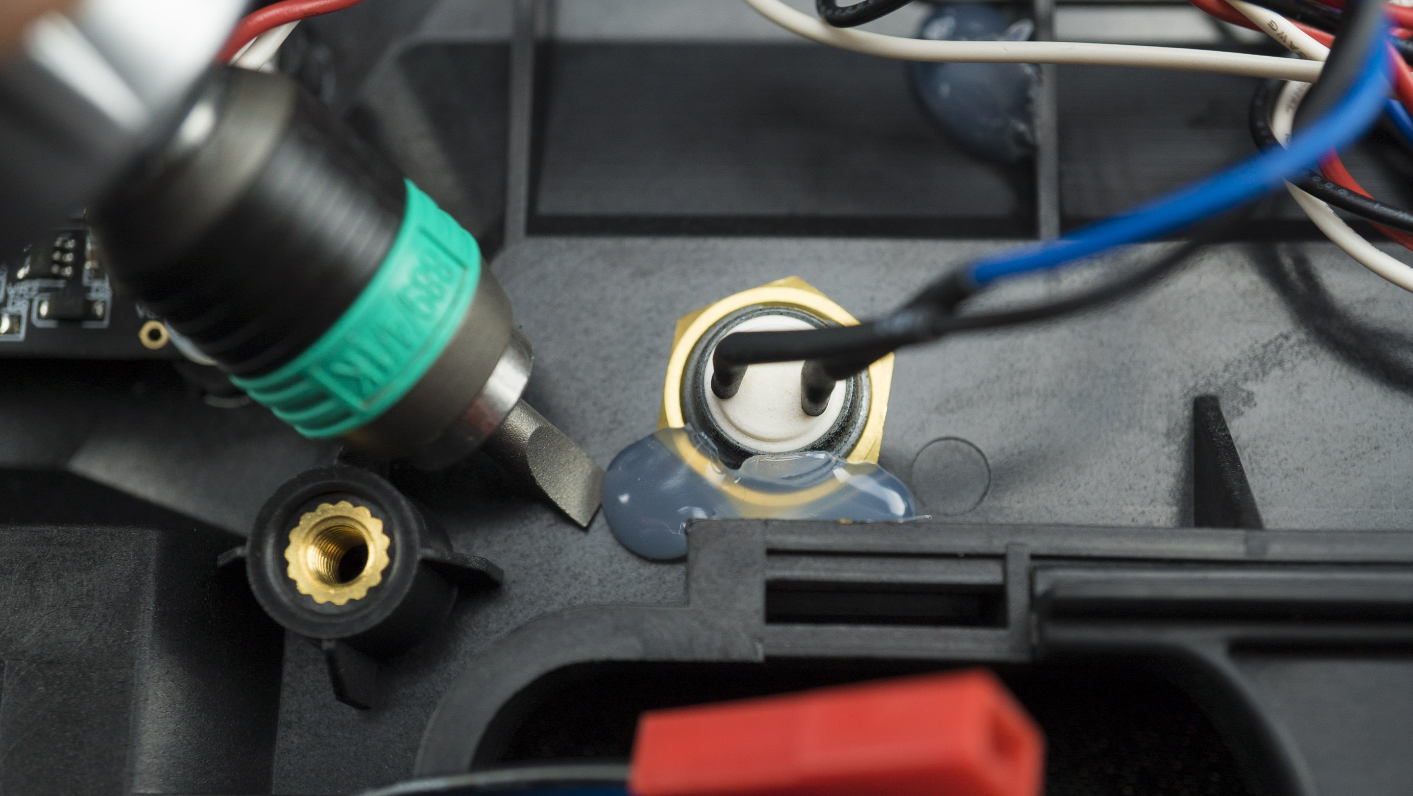
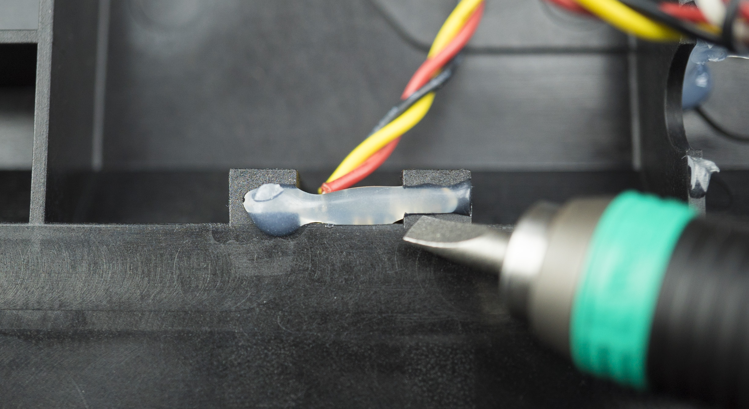
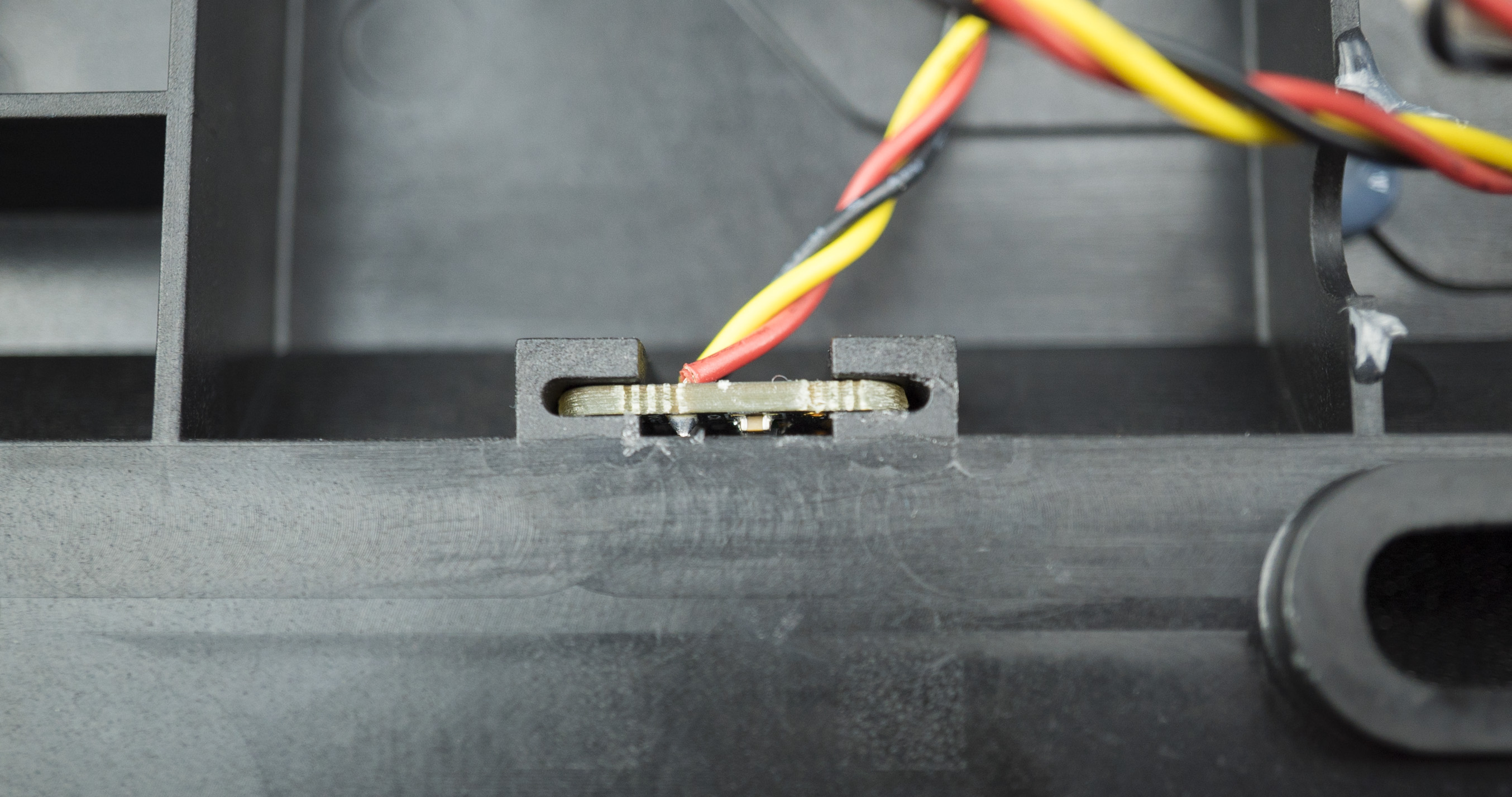
- Using the 4mm flat head attachment and the torque driver, carefully pry out the glue holding the button, cable or battery in place.
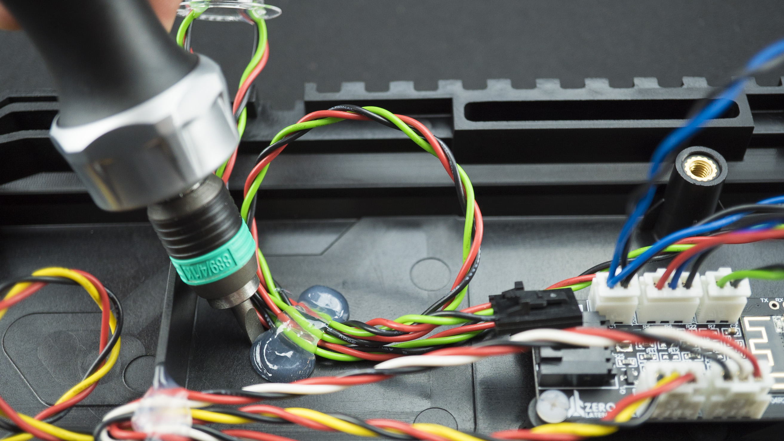
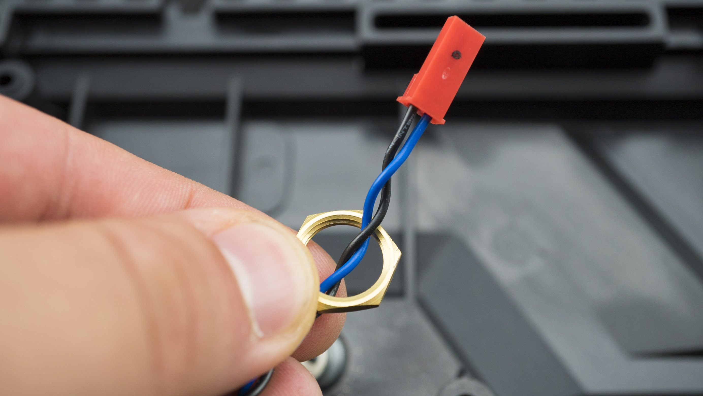
- Unplug and remove the faulty button, cable or battery.
Power Distribution PCB
- Disconnect the cables connected to the PCB.
- Unscrew the PCB from the controller.
- Carefully remove the PCB.
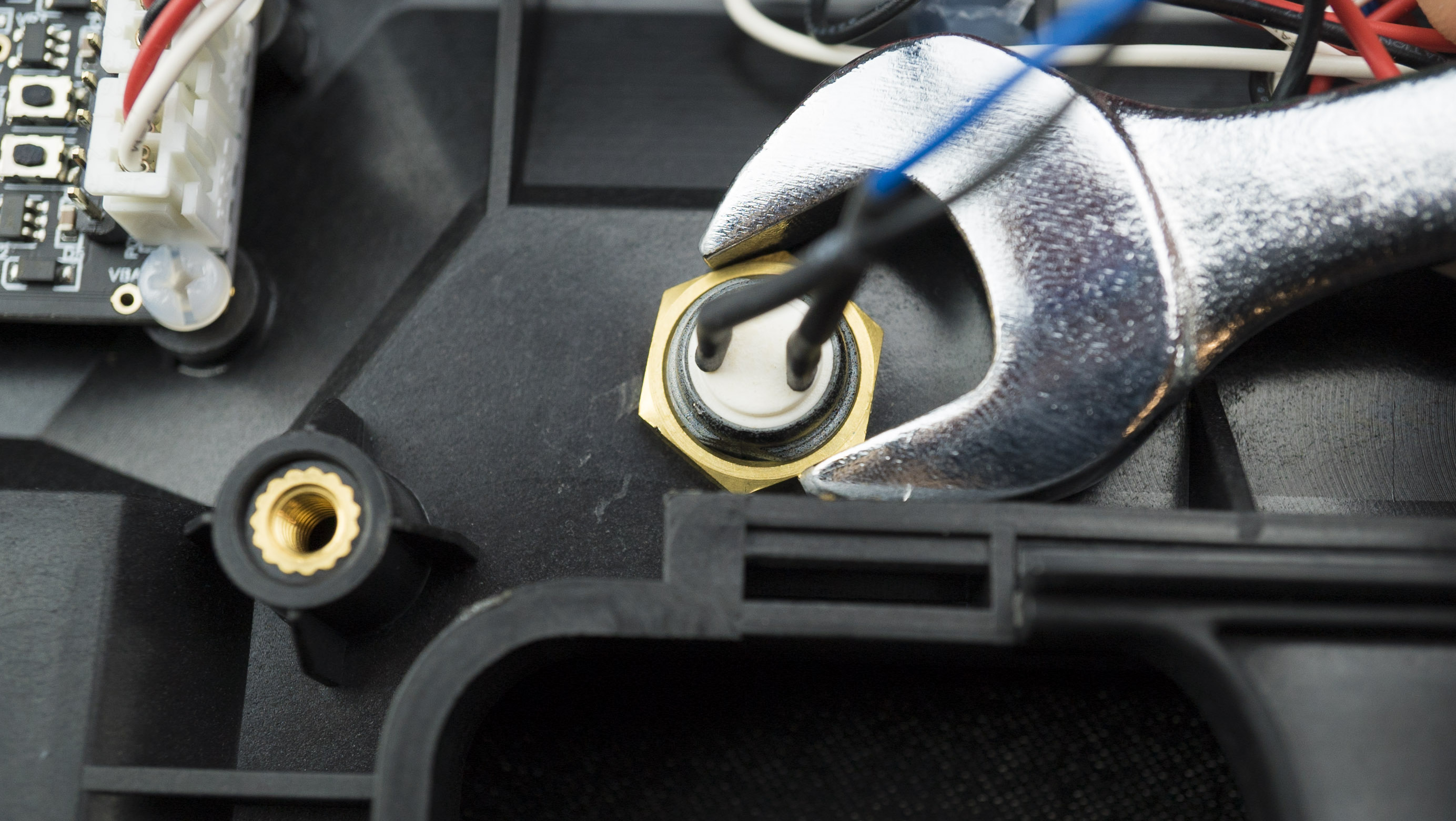
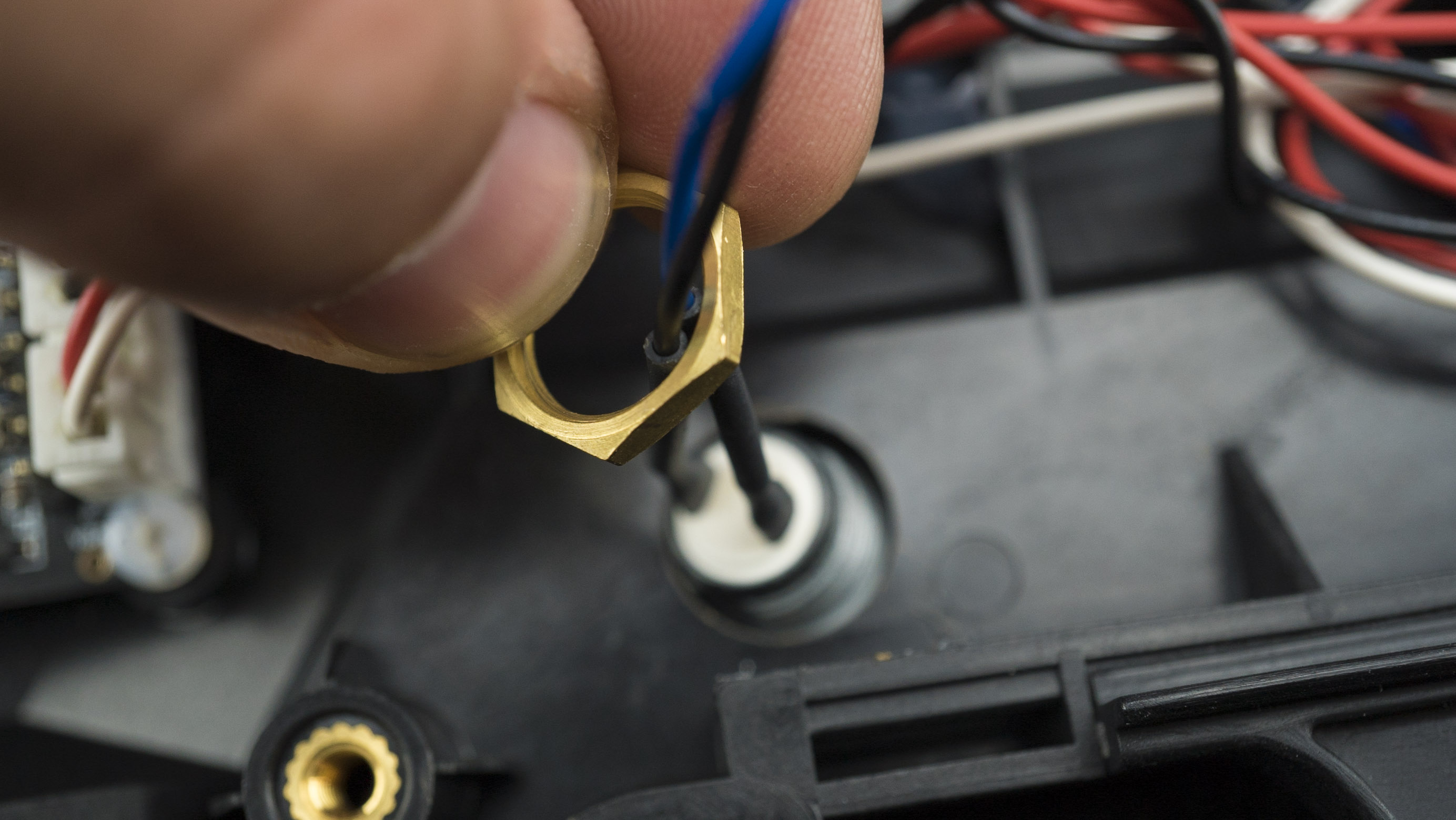
Mode A
- Remove the glue holding the cable in place.
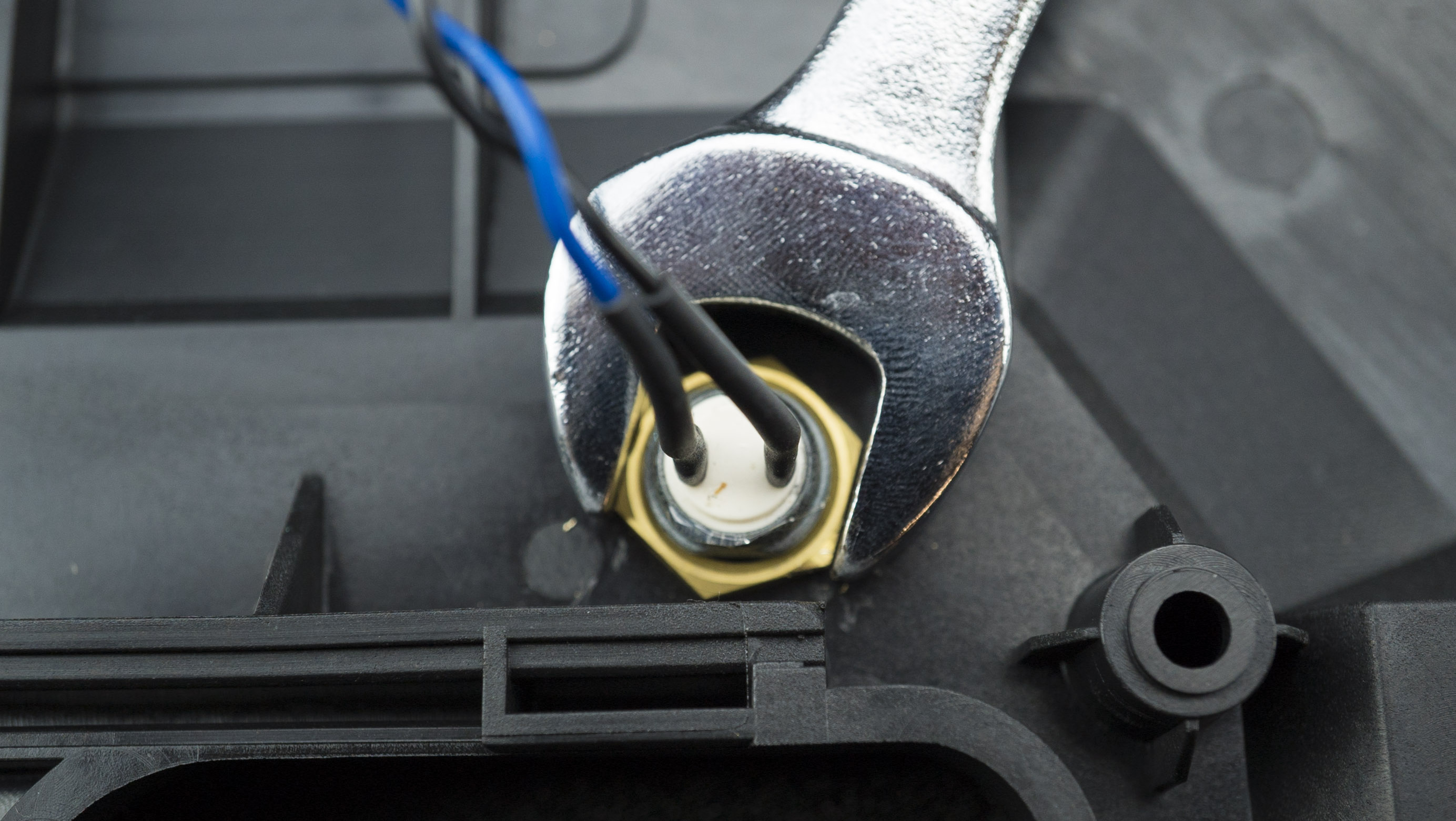
- Using the spanner, remove the nut.
Mode B
- Remove the glue holding the cable in place.
- Using the spanner, remove the nut.
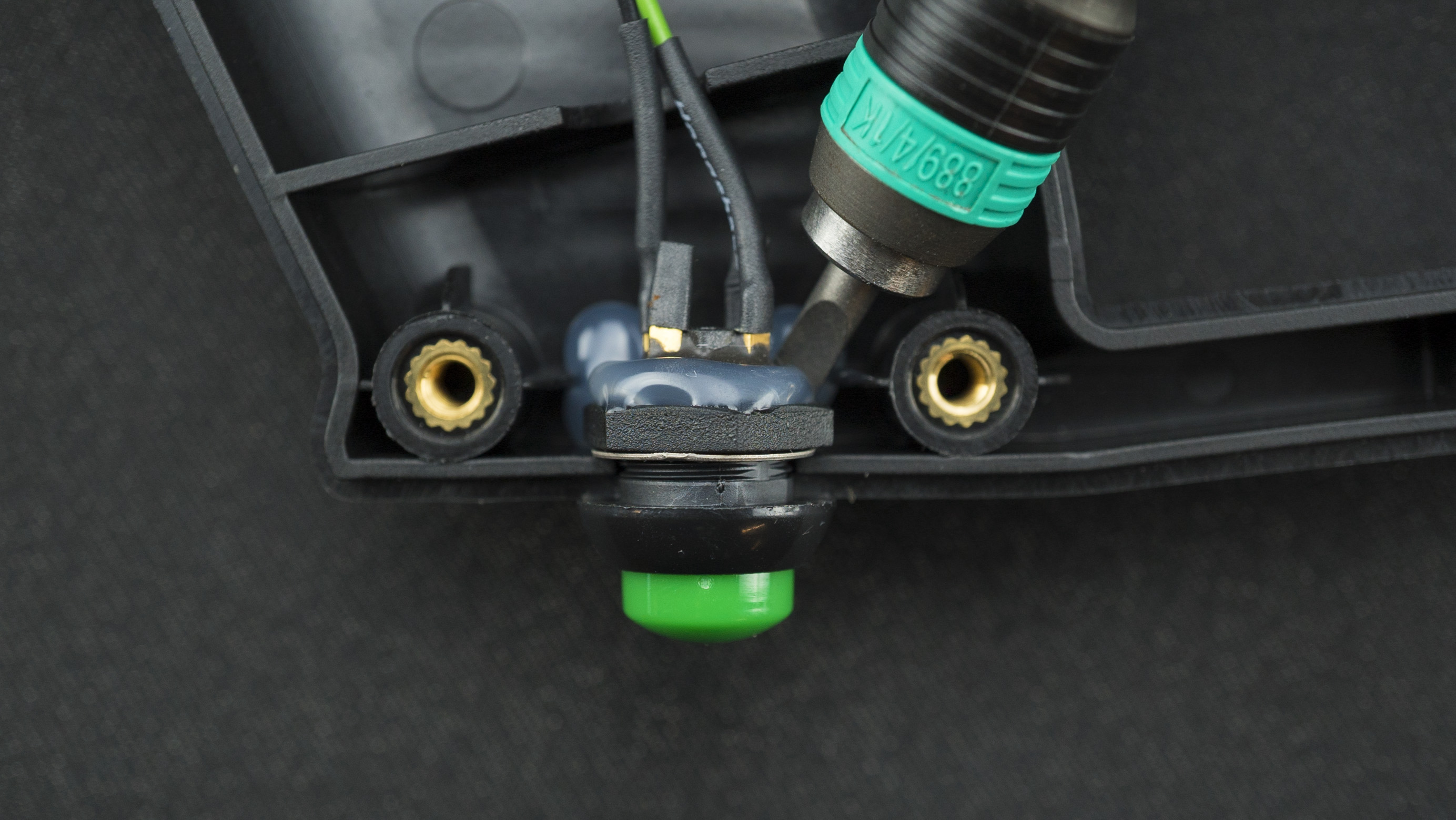
Reload
- Remove the trigger to gain access to the cable.
- Carefully remove the glue and unscrew the reload button.
Trigger
- Remove the two nylon crews.
Pump A
- Carefully remove the glue and remove the pump A.
Pump B
- Carefully remove the glue and remove the pump B.
LED
- Carefully remove the glue and remove the LED.

Battery
- Remove the screws holding the battery in place.
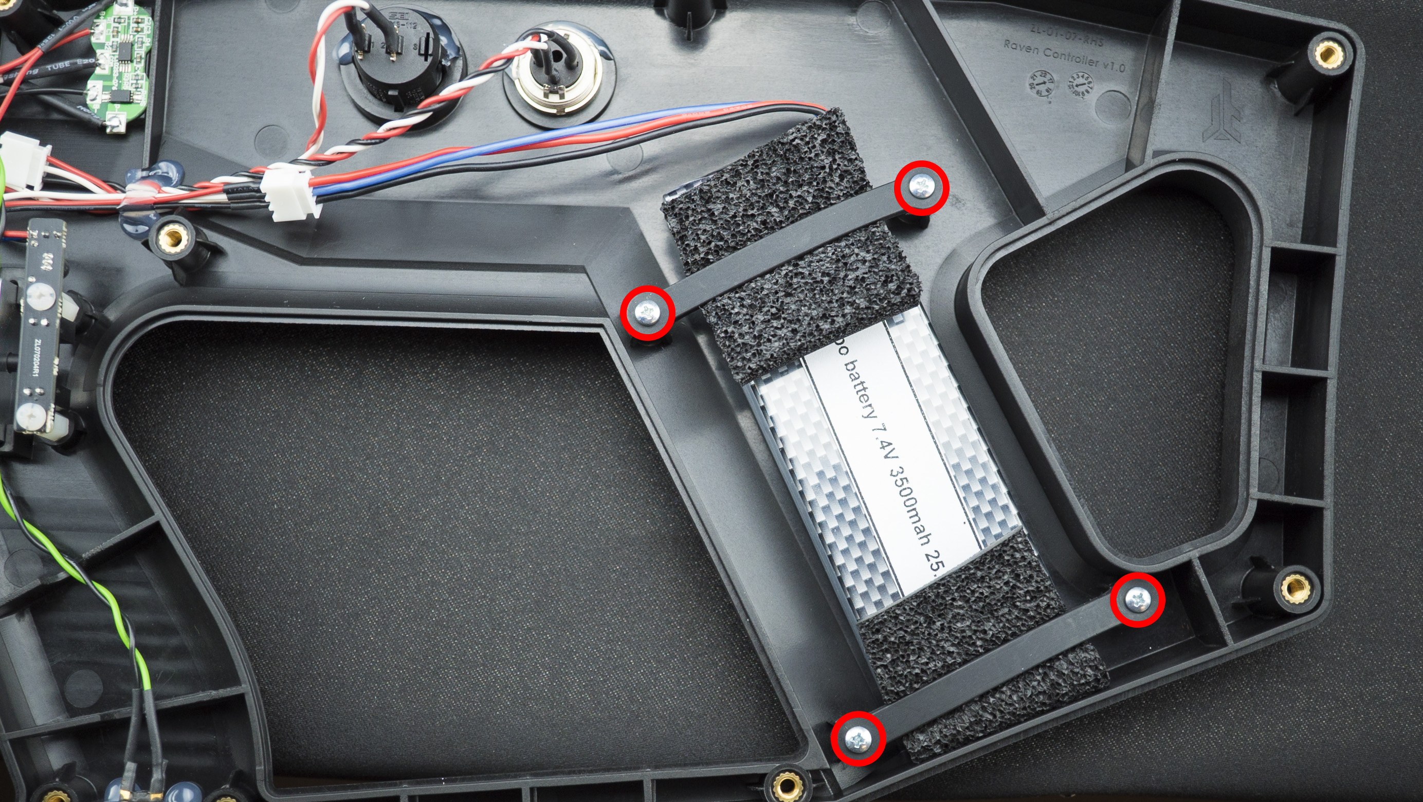
- Unplug the cable and remove the battery.
USB C Cable
- Remove all the connections.
- Remove carefully from controller.
Master PCB
- Remove all the connections.
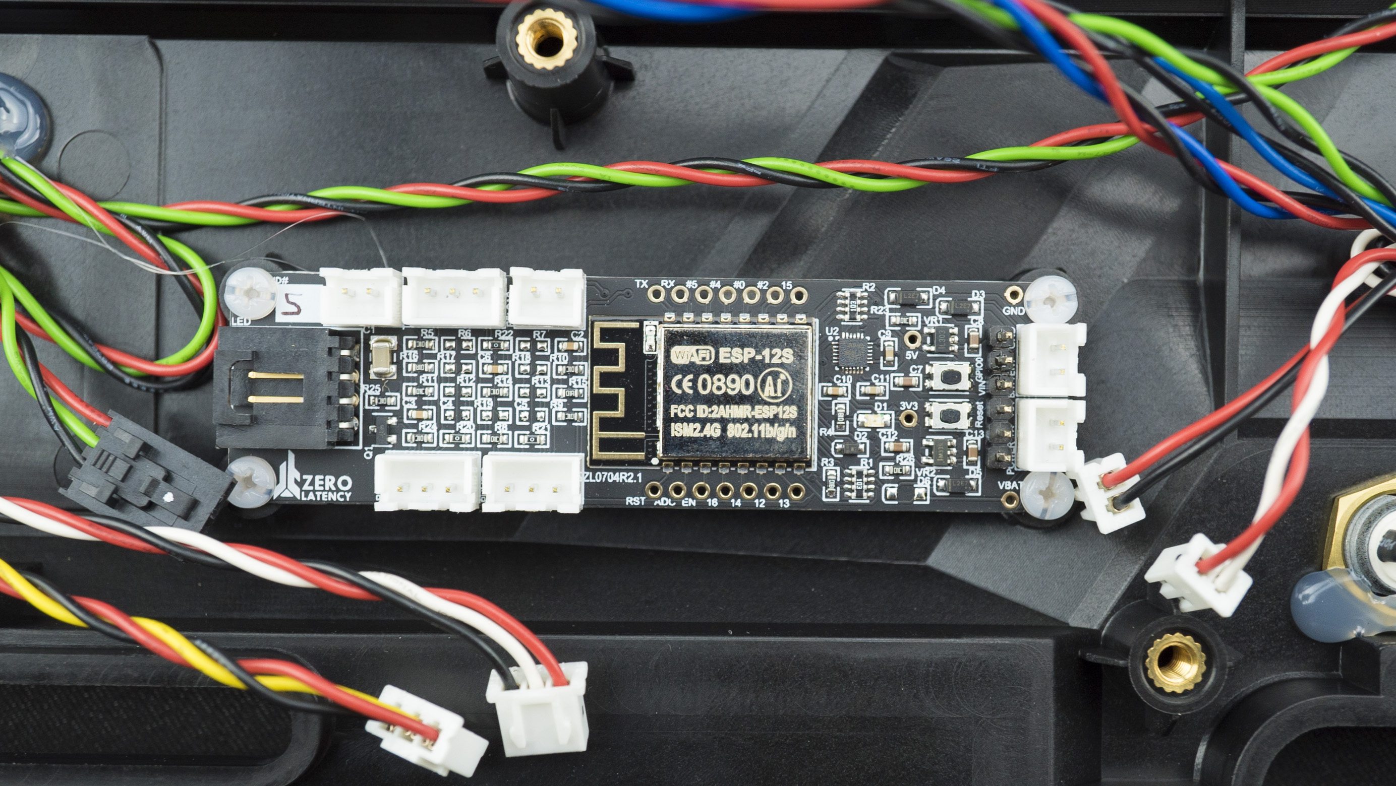
- Remove all the nylon screws then remove the Master PCB.
- Once complete, plug in and secure the new button or cable using the hot glue gun.
- Test the cable using the debug mode.
This resolved the issue
- Continue to Step 5.
This did not resolve the issue
- Log a ticket to Zero Latency Support.
Step 5: Close the controller
- Make sure that all cables are plugged in and insert the bump-on onto the controller.
- Carefully close the controller, ensure that no cables can get pinched.
- Insert and tighten the top six screws and the bottom seven screws (remember that the screw closest to the grip is the smallest screw).
- Insert the tracking ball into the seat and secure the LED tracking ball clamps. The battery wire will fit through a little gap in the clamp.
- Using the 3mm hex attachment and the torque driver, insert the two screws and nuts (the torque driver will click once the screws are tight enough).
- Make sure the slide grip with the magnet is installed on the right-hand side otherwise the pump-action will not work.
Caution
The magnet activates the Pump A and Pump B sensors, if it is not placed on the right-hand side, the pump-action will not work.
- Place the two ball bearing on top of the two screws.
- Align the controller and attach the slide grip, repeat for the opposite side. Secure the three screws.
Caution
Do not overtighten these screws as they are responsible for how much resistance is in the pump-action movement.
- Slide on the Tracker mount.
- Connect the USB C cable to the Tracker.
- Slide the Tracker into the mount.
- Screw the mount onto the controller.
- The controller assembly is now complete, please test the controller before returning to operations.
Article Keywords/Phrases:

How to fix a cable or button
Open the controller
Close the controller
Controller Debug mode
Comments
0 comments
Article is closed for comments.